


B-2
B-2
OPERATION
● No external shielding gas is required when used
with Lincoln Innershield .035” (0,9 mm) NR
®
-211-
MP electrode.
● Spindle accommodates both 8 in. (200 mm) diame-
ter and 4 in. (100 mm) diameter spools of wire.
WELDING CAPABILITY
The SP 170-I is rated at 125 amps, 20.25 volts, at
25% duty cycle on a ten minute basis. It is capable of
higher output currents at lower duty cycles. Actual
welding outputs will range between 30 and 175 amps
for the recommended processes.
LIMITATIONS
Arc Gouging cannot be performed with the SP 170-I.
The SP 170-I is not recommended for pipe thawing or
TIG welding.
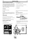
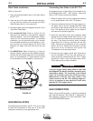
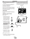
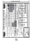
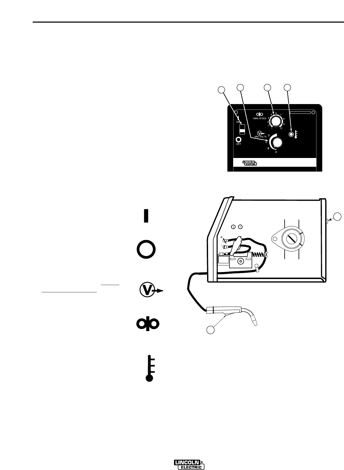
CONTROLS AND SETTINGS
Refer to Figures B.1a
(Items 1 thru 4)
1.
Power ON/OFF Switch — When
the power is on the fan motor
will run and air will be exhaust-
ed out the louvers in the front of
the machine. The welding out-
put and wire feeder remain off
until the gun trigger is pressed.
2.
Voltage Control — A 5-position
tap selector switch gives full
range adjustment of power
source output voltage. Do not
switch while welding.
3.
Wire Speed Control — Controls
the wire feed speed from 50 –
400 in/min (1.3 – 10.2 m/min).
The control can be preset on
the dial to the setting specified
on the SP 170-I Application
Chart located on the inside of
the wire feed section door.
4.
Temperature Light — Indicates
thermostat has cut the output.
The fan will be running.
Thermostat resets automatical-
ly.
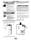
(Refer to Figure B.1b, Items 5,6)
5. Circuit Breaker – Protects machine from damage if
maximum output is exceeded. Button will extend
out when tripped (Manual reset).
OFF
ON
ARC VOLTS
WIRE SPEED
6. Gun Trigger - Activates welding output, wire feed,
and gas solenoid operation. Releasing the trigger
deactivates welding and simultaneously activates
the “burnback” function so that the welding wire
does not stick in the weld puddle.
FIGURE B.1a
FIGURE B.1b
SP 170 - I
1
2 3 4
E
5
6
SP 170-I