


A-4
INSTALLATION
EAGLE 10,000
A-4
ANGLE OF OPERATION
Internal combustion engines are designed to run in a
level condition which is where the optimum perfor-
mance is achieved. The maximum angle of operation
for the engine is 15 degrees from horizontal in any
direction. If the engine is to be operated at an angle,
provisions must be made for checking and maintain-
ing the oil at the normal (FULL) oil capacity in the
crankcase in a level condition.
When operating at an angle, the effective fuel capaci-
ty will be slightly less than the specified 9 gal (34 L).
LIFTING
The EAGLE 10,000 weighs approximately 575 lbs.
(281kg) with a full tank of gasoline. A lift bail is
mounted to the machine and should always be used
when lifting the machine.
ADDITIONAL SAFETY PRECAUTIONS
• Lift only with equipment of adequate
lifting capacity.
• Be sure machine is stable when lift-
ing.
• Do not lift this machine using lift bail
if it is equipped with a heavy acces-
sory such as trailer or gas cylinder.
FALLING • Do not lift machine if lift bail is
EQUIPMENT can damaged.
cause injury. • Do not operate machine while
suspended from lift bail.
-----------------------------------------------------------------------
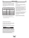
HIGH ALTITUDE OPERATION
If the EAGLE 10,000 will be consistently operated at
altitudes above 5000 ft, a carburetor jet designed for
high altitudes should be installed. This will result in
better fuel economy, cleaner exhaust, and longer
spark plug life. It will not
give increased power which
is decreased at higher altitudes. Engine horsepower
is reduced by 3.5% per 1000ft.(3280m) for altitudes
above 377 ft.(1237m).
Do not operate a EAGLE 10,000 with a high alti-
tude jet installed at altitudes below
5000ft.(16,404m). This will result in the engine
running too lean and result in higher engine oper-
ating temperatures which can shorten engine life.
-----------------------------------------------------------------------
Contact your local Kohler Authorized Dealer for high
altitude jet kits that are available from the engine
manufacturer.
Muffler Relocation
• Shut off welder and allow muffler to cool before
touching muffler.
------------------------------------------------------------------------
The EAGLE 10,000 is shipped with the exhaust com-
ing out on the left side. The exhaust can be changed
to the opposite side by removing the two screws that
hold the exhaust port cover in place and installing the
cover on the opposite side. (Operating the EAGLE
10,000 without the cover in place will result in a higher
noise level and no increase in machine output.)
LOCATION / VENTILATION
The welder should be located to provide an unrestrict-
ed flow of clean, cool air to the cooling air inlets and to
avoid heated air coming out of the welder recirculating
back to the cooling air inlet. Also, locate the welder so
that engine exhaust fumes are properly vented to an
outside area.
STACKING
EAGLE 10,000 machines cannot be stacked.
CONNECTION OF LINCOLN ELECTRIC
WIRE FEEDERS
Note: A constant voltage (CV) power source is rec-
ommended for wire feeder applications. The
LN-15 and LN-25 may be used with a constant
current (CC) power source, such as the EAGLE
10,000, for non-critical applications where weld
quality and deposition properties are not critical.
Shut off welder before making any electrical
connections.
------------------------------------------------------------------------
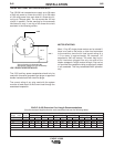
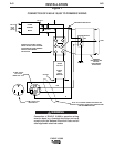
WIRE FEED CONNECTION OF LN-15 ACROSS-
THE-ARC WIRE FEEDER
The LN-15 has an internal contactor and the electrode
is not energized until the gun trigger is closed. When
the gun trigger is closed the wire will begin to feed
and the welding process is started.
a. Shut the welder off.
b. For electrode Positive, connect the electrode
cable to the "+" terminal of the welder and work
cable to the "-" terminal of the welder. For elec-
trode Negative, connect the electrode cable "-"
terminal of the welder and work cable to the "+"
terminal of the welder.
CAUTION
WARNING
WARNING
WARNING