


A-3
INSTALLATION
VANTAGE
®
500 (CE)
A-3
SAFETY PRECAUTIONS
Only qualified personnel should install,
use, or service this equipment.
Do not attempt to use this equipment until you
have thoroughly read the engine manufacturer’s
manual supplied with your welder. It includes
important safety precautions, detailed engine
starting, operating and maintenance instructions,
and parts lists.
------------------------------------------------------------------------
ELECTRIC SHOCK can kill.
• Do not touch electrically live parts or
electrode with skin or wet clothing.
• Insulate yourself from work and
ground
• Always wear dry insulating gloves.
------------------------------------------------------------------------
ENGINE EXHAUST can kill.
• Use in open, well ventilated areas or
vent exhaust outside.
------------------------------------------------------------------------
MOVING PARTS can injure.
• Do not operate with doors open or
guards off.
• Stop engine before servicing.
• Keep away from moving parts.
------------------------------------------------------------------------
See additional warning information at
front of this operator’s manual.
WARNING
VRD (VOLTAGE REDUCTION DEVICE)
The VRD feature provides additional safety in the CC-Stick
mode especially in an environment with a higher risk of
electric shock such as wet areas and hot humid sweaty
conditions.
The VRD reduces the OCV (Open Circuit Voltage) at the
welding output terminals while not welding to less than
32V for (Codes 11298, 11299)
,
30V for
(
Codes 11524,
11525
, 11574, 11575)
DC when the resistance of the out-
put circuit is above 200 ohms.
The VRD requires that the welding cable connections be
kept in good electrical condition because poor connections
will contribute to poor starting. Having good electrical con-
nections also limits the possibility of other safety issues
such as heat-generated damage, burns and fires.
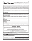
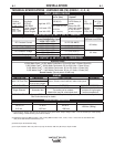
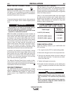
The machine is shipped with the VRD switch in the “Off”
position. To turn it “On” or “Off”:
• Turn the engine “Off”.
• Disconnect the negative battery cable.
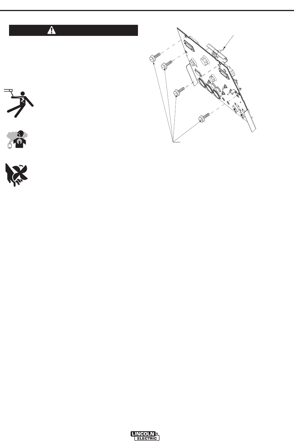
• Lower the control panel by removing 4 front
panel screws.
(See Figure A.1)
• Place the VRD switch in the “On or “Off” position.
(See Figure A.1)
With the VRD switch in the “On” position, the VRD lights
are enabled.
LOCATION AND VENTILATION
The welder should be located to provide an unrestrict-
ed flow of clean, cool air to the cooling air inlets and to
avoid restricting the cooling air outlets. Also, locate
the welder so that the engine exhaust fumes are prop-
erly vented to an outside area.
STACKING
VANTAGE® 500 (CE) machines cannot be stacked.
ANGLE OF OPERATION
Engines are designed to run in the level condition
which is where the optimum performance is achieved.
The maximum angle of continuous operation is 25
degrees in all directions, 35 degrees Intermittent (less
than 10 minutes continuous) in all directions. If the
engine is to be operated at an angle, provisions must
be made for checking and maintaining the oil level at
the normal (FULL) oil capacity in the crankcase.
When operating the welder at an angle, the effective
fuel capacity will be slightly less than the amount
specified.
LIFTING
The VANTAGE® 500 (CE) weighs approximately
1405 lbs.(638kg.) for (Codes 11298, 11299),
1440lbs.(653kg.) for (Codes 11524, 11525, 11574,
11575) with a full tank of fuel 1290lbs. (586kg) less
fuel. A lift bail is mounted to the machine and should
always be used when lifting the machine.
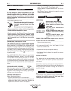
(
VRD)-VOLTAGE REDUCTION DEVICE
S
WITCH IS LOCATED IN THIS AREA.
REMOVE 4 FRONT PANEL
SCREWS TO ACCESS
(
VRD) SWITCH
FIGURE A.1