


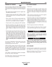
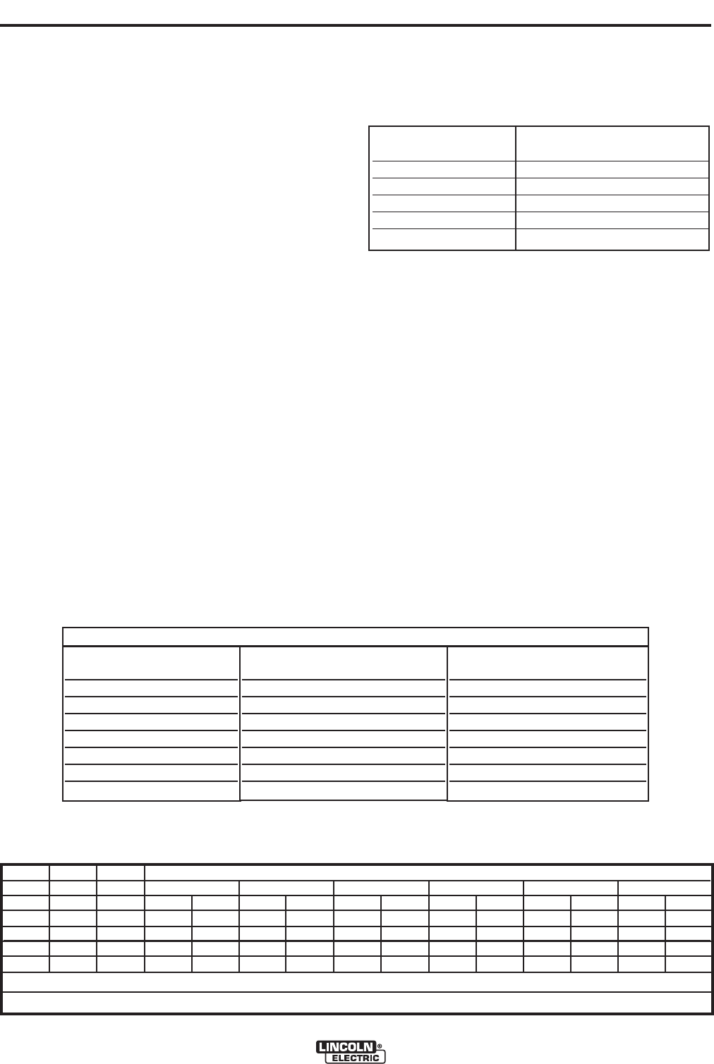
Carbon Diameter
Current Range (DC, electrode
positive)
1/8"(3.2mm) 60-90 Amps
5/32"(4.0mm) 90-150 Amps
3/16"9(4.8mm) 200-250 Amps
1/4"(6.4mm) 300-400 Amps
3/8"(10.0mm) 400-Max.Amps
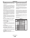
AUXILIARY POWER:
Start the engine and set the IDLER control switch to
the desired operating mode. Full power is available
regardless of the welding control settings providing no
welding current is being drawn.
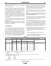
Simultaneous Welding and Auxiliary Power Loads
The auxiliary power ratings are with no welding load.
Simultaneous welding and power loads are specified
in Table B.5.
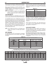
VANTAGE® 500 (CE) Extension Cord Length Recommendations
(Use the shortest length extension cord possible sized per the following table.)
Current
(Amps)
15
20
15
20
44
Voltage
Volts
120
120
240
240
240
Load
(Watts)
1800
2400
3600
4800
9500
30
60
(9)
(18)
40
30
75
60
(12)
(9)
(23)
(18)
75
50
150
100
50
(23)
(15)
(46)
(30)
(15)
125
88
225
175
90
(38)
(27)
(69)
(53)
(27)
175
138
350
275
150
(53)
(42)
(107)
(84)
(46)
300
225
600
450
225
(91)
(69)
(183)
(137)
(69)
Maximum Allowable Cord Length in ft. (m) for Conductor Size
Conductor size is based on maximum 2.0% voltage drop.
14 AWG 12 AWG 10 AWG 8 AWG 6 AWG 4 AWG
VANTAGE
®
500 (CE)
B-7
OPERATION
B-7
This will keep the "Solid State" contactor open and provide a
"cold" electrode until the Amptrol or Arc Start Switch is pressed.
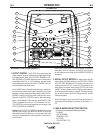
When using the TIG Module, the OUTPUT CONTROL on the
VANTAGE® 500 (CE) is used to set the maximum range of the
CURRENT CONTROL on the TIG Module or an Amptrol if con-
nected to the TIG Module.
NOTE: The TIG process is to receive a low voltage welding
process. There is no difference in operation with the
VRD “On” or “Off” for this mode. For indicator light oper-
ation, see table B.1.
WIRE WELDING-CV
Connect a wire feeder to the VANTAGE® 500 (CE) according
to the instructions in INSTALLATION INSTRUCTIONS Section.
The VANTAGE® 500 (CE) in the CV-WIRE mode, permits it to
be used with a broad range of flux cored wire (Innershield and
Outershield) electrodes and solid wires for MIG welding (gas
metal arc welding). Welding can be finely tuned using the ARC
CONTROL. Turning the ARC CONTROL clockwise from –10
(soft) to +10 (crisp) changes the arc from soft and washed-in to
crisp and narrow. It acts as an inductance/pinch control. The
proper setting depends on the procedure and operator prefer-
ence. Start with the dial set at 0.
NOTE: In the CV-Mode with VRD “On”, the OCV(Open Circuit
Voltage) is not reduced. For indicator light operation,
see table B.1.
ARC GOUGING
The VANTAGE® 500 (CE) can be used for arc gouging.
For optimal performance, set the MODE switch to ARC
GOUGING.
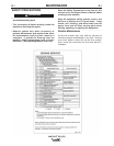
TABLE B.5
TABLE B.6
WELDING OUTPUT
(AMPS)
NOT WELDING
100
200
300
400
450
Max.
AUXILIARY POWER OUTPUT
(WATTS)
14,500
11,100
8,900
4,900
700
0
0
AUXILIARY POWER OUTPUT
(AMPS @ 400V, 3-PHASE)
21.0
17.5
12.8
7.1
1.0
0
0
SIMULTANEOUS WELDING AND AUXILIARY POWER OUTPUT
Set the OUTPUT CONTROL knob to adjust output
current to the desired level for the gouging electrode
being used according to the ratings in the following
Table B.4.
TABLE B.4
The ARC CONTROL is not active in the ARC GOUG-
ING Mode. The ARC CONTROL is automatically set
to maximum when the ARC GOUGING mode is
selected which provides the best ARC GOUGING per-
formance.
NOTE: With the VRD switch in the “ON” position there
is no output in the Arc Gouging Mode. For indicator
light operation, see table B.1.