


A-6
INSTALLATION
POWER WAVE® 405M
A-6
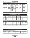
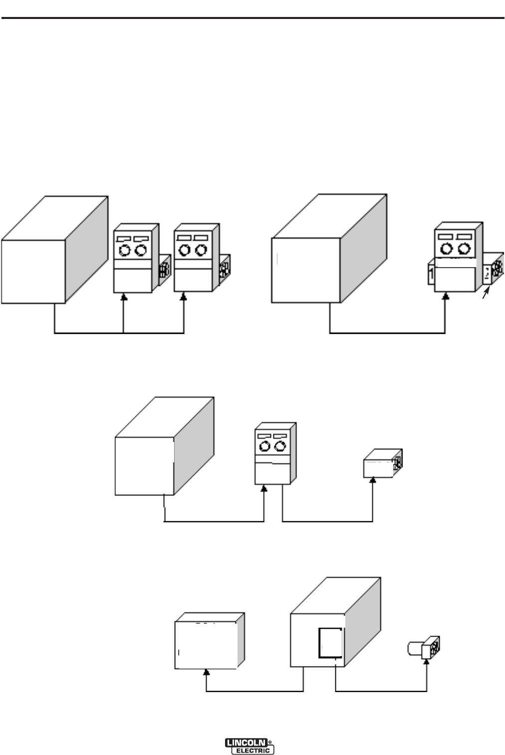
CONFIGURING THE SYSTEM
The power source will “Auto Map” the system eliminat-
ing most of the need to set DIP switches to configure
the system.
If a system can not be “Auto Mapped” then the status
light on the power source will blink green fast and the
welder output will be disabled.
If a system can not be “Auto Mapped” then the status
light on the power source will blink green fast and the
welder output will be disabled. If a system is not
“Auto-mappable”, then consult the instruction manual
for the accessory being used for configuration infor-
mation about DIP switch settings, or consult your local
Lincoln sales representative.
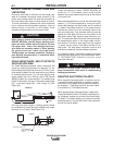
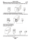
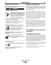
POWER WAVE®
405M
ROBOT
PLC CONTROLLER
ANALOG INTERFACE
etc.
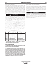
POWER WAVE® 405M
POWER WAVE
®
405M
POWER WAVE®
405M
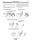
FEED HEAD
FEED HEAD 1
CONTROL BOX
SINGLE HEAD FEEDER DUAL HEAD FEEDER
SINGLE HEAD BOOM FEEDER
PF-10R
SINGLE HEAD BOOM FEEDER
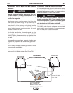
UP TO 4 WIRE FEEDERS
ALLOWED
UP TO 4 FEED HEADS
ALLOWED
WIRE
DRIVE
MODULE