


A-10
INSTALLATION
POWER WAVE® 405M
A-10
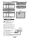
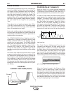
I / O RECEPTACLE SPECIFICATIONS
TABLE A.2
WIRE FEEDER RECEPTACLE
PIN LEAD# FUNCTION
A 53 Communication Bus L
B 54 Communication Bus H
C 67A Electrode Voltage Sense
D 52 0vdc -
E 51 +40vdc +
TABLE A.3
VOLTAGE SENSE RECEPTACLE
PIN LEAD# FUNCTION
3 21A Work Voltage Sense
TABLE A.4
RS232 RECEPTACLE
PIN LEAD# FUNCTION
2 253 RS232 Receive
3 254 RS232 Transmit
4#Pin5
5#Pin4
6 # # Pin20
20 # # Pin6
7 251 RS232 Common
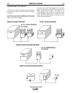
DIP SWITCH SETTINGS AND LOCATIONS
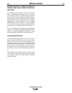
DIP switches on the P.C. Boards allow for custom configuration of
the POWER WAVE®. To access the DIP switches:
ELECTRIC SHOCK can kill.
1. Turn off power to the power source at the dis-
connect switch.
• Insulate yourself from the work and ground.
• Always wear dry insulating gloves.
------------------------------------------------------------------------------------------
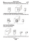
2. Remove the wrap around cover from the power source.
3. The control board is on the center assembly facing the case front.
Locate the 8-position DIP switch and look for switch 8 of the DIP
switch.
4. Using a pencil or other small object, slide the switch to the OFF
position if the work sense lead is NOT connected. Conversely, slide
the switch to the ON position if the work sense lead is present.
5. Replace the wrap around and screws. The PC board will “read” the
switch at power up, and configure the work voltage sense lead
appropriately.
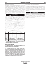
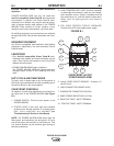
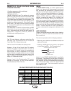
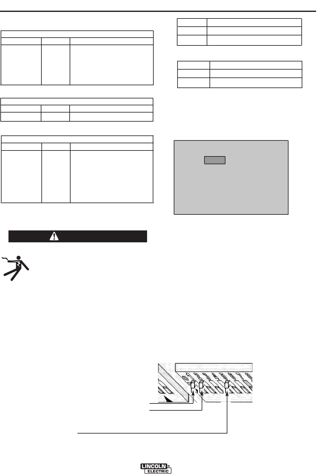
CONTROL BOARD DIP SWITCH:
switch 1 = reserved for future use
switch 2 = reserved for future use
switch 3 = equipment group 1 selcted (default=off)
switch 4 = equipment group 2 selcted (default=off)
switch 5 = reserved for future use
switch 6 = reserved for future use
switch 7 = auto mapping
switch 8 = work sense lead
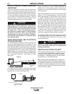
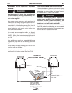
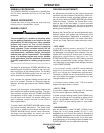
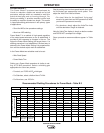
(See Figure A.8 for Dual Head Boom Feeder)
switch 8*
work sense lead
off work sense lead not connected
on work sense lead connected
*Factory setting for Switch 8 is OFF.
switch 7
auto mapping
off auto mapping enable-default
on auto mapping disabled
CONTROL BOARD (DIP Switch Location)
FIGURE A.7
WARNING
}
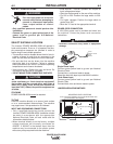
40VDC
FIGURE A.8