


%!&,&&
##&#!&&*+ !$R(*'
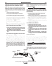
&', ,;8@4K<@H@J<E8F<M89BE4#4A7#
<FT,;8E89BE8G;8T4A7T?<A8EF4E8ABG
<A6?H787J<G;G;8F8><GF
,;<F F6E8J F;BH?7 BA?L 58 :8AG?L G<:;G8A87
'I8EG<:;G8A<A:J<??FC?<GBE6B??4CF8G;8?<A8E4A764HF8
CBBEJ<E89887<A:
-------------------------------------------------------------------------------
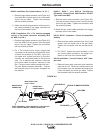
5. Be sure the cable is straight and then trim the liner
flush with the end of the gun tube.
6. Remove the gun tube and trim an additional 9/16”
(12.7 mm) of material from the end of the liner (a 9/16”
gage is included on the wrench supplied with the gun).
7. Replace the gun tube and tighten the clamping screw
to secure it.
8. Reassemble the tip holder, insulator, and contact tip
onto the end of the gun tube.
-&,-+&&'22$+
1. Replace worn contact tips as required.
2. Remove spatter from from contact tip, tip holder, insu-
lator and gun tube after each 10 minutes of arc time or
as required.
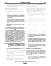
3. To remove gun tube from gun, loosen socket-head
clamping screw in handle with 3/16" (4.8 mm) Allen
wrench.
4. Pull gun tube out from gun handle. To reinstall, insert
the gun tube, push in as far as possible, and retighten
clamping screw.
$$&!&
Clean cable liner after using approximately 150 (68 kg)
pounds of electrode. Remove the cable from the wire feed-
er and lay it out straight on the floor. Remove the contact tip
from the gun. Using an air hose and only partial pressure,
gently blow out the cable liner from the tip holder end.
QK68FF<I8CE8FFHE84GG;8FG4EG@4L64HF8G;87<EGGB
9BE@4C?H:
-------------------------------------------------------------------------------
Flex the cable over its entire length and again blow out the
cable. Repeat this procedure until no further dirt comes out.
-,!'&
-,!'&
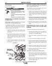
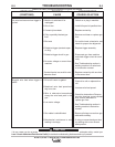
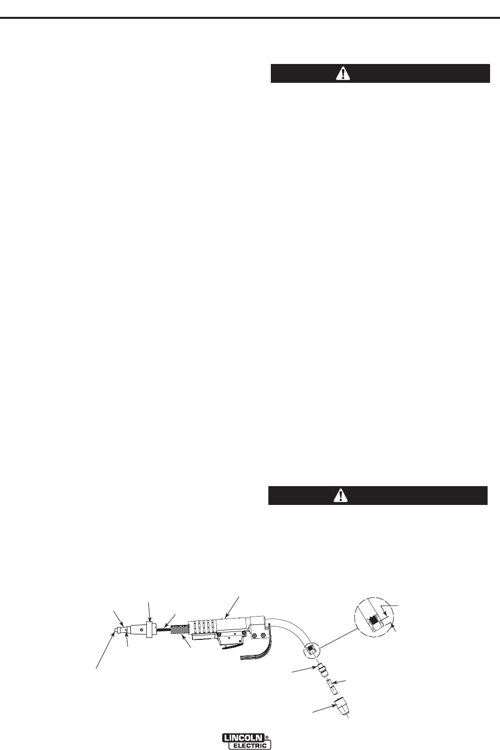
GUN HANDLE
Liner
CABLE
TIP HOLDER
TIP
INSULATOR
FEEDER END
CABLE HANDLE
BRASS CABLE
CONNECTOR
SET SCREW
LINER ASSEMBLY (LINER BUSHING TO BE SEATED
TIGHT AGAINST BRASS CABLE CONNECTOR
L
I
N
E
R
T
R
I
M
L
E
N
G
T
H
9
/
1
6
"
(
1
4
.
3
m
m
)
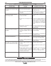
GUN HANDLE
Liner
CABLE
TIP HOLDER
TIP
INSULATOR
FEEDER END
CABLE HANDLE
BRASS CABLE
CONNECTOR
SET SCREW
LINER ASSEMBLY (LINER BUSHING TO BE SEATED
TIGHT AGAINST BRASS CABLE CONNECTOR
L
I
N
E
R
T
R
I
M
L
E
N
G
T
H
9
/
1
6
"
(
1
4
.
3
m
m
)
<:HE8
*%'.$!&+,$$,!'&&,*!%%!&
!&+,*-,!'&+'*V%&-%R$!&*+
&', The variation in cable lengths prevents the inter-
changeability of liners. Once a liner has been cut for a par-
ticular gun, it should not be installed in another gun, unless
it can meet the liner cut off length requirement. Liners are
shipped with the jacket of the liner extended the proper
amount.
1. Remove the insulator and tip holder.
2. Lay the gun and cable straight on a flat surface.
For all connectors except K466-3, K466-4 and K613-3:
Loosen set screw located in the brass cable connector at
the wire feeder end of the cable using the same 5/64 (2.0
mm) Allen wrench. Pull liner out of cable.
'*
For K466-3, K466-4 and K613-3 connectors:
Remove the connector cap with the wrench provided.
Pull liner out of cable. If the liner is going to be replaced
with a different size liner, loosen set screw on the con-
nector cap and remove piece of liner material.
3. Insert a new untrimmed liner into the connector end of
the cable. Be sure the liner bushing is stenciled
appropriately for the wire size being used.
4. Be sure to fully seat the liner bushing in the connector
and:
For all connector kits except K466-3, K466-4 and K613-
3, tighten the set screw in the cable connector.
'*
For K466-3, K466-4 and K613-3, screw in the connector
cap provided in the kit until it seats on the face of the
bushing. Then insert the appropriate piece of liner mate-
rial into the connector cap and tighten the set screw.
Three pieces of liner material are included in these con-
nector kits to help guide the electrode through the con-
nector cap. The piece with the smallest inner diameter is
designed for .045" (1.2 mm) maximum diameter elec-
trode and the other liners fit the following wires (maxi-
mum size) in order of increasing inside diameter: 1/16”
(1.6 mm), 5/64” (2.0 mm), 3/32” (2.4 mm) and 1/8” (3.2
mm).