


INSTALLATION
MAGNUM 300 & 400
c. For L-Tec machines that require trigger lead con-
nections to be made at a terminal strip located with-
in the machine (L-Tec 225), a gun control cable with
forked terminals is provided. Connect the terminat-
ed leads to the terminal strip. For a machine that
requires a twist-lock gun control cable connection,
continue to use the L-Tec gun control cable provid-
ed with the L-Tec wire feeder connector assembly.
Connect the twist-lock plug to the proper receptacle
on the machine.
K466-6, K466-7, K466-9 and K466-10 Installation
(Wirematic, Hobart Series 2000 Feeders, SP100T
Type and Lincoln 10 Series Feeders)
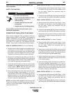
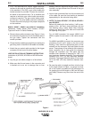
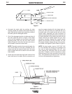
a. Remove brass cable connector (see Figure 1) from
the connector kit and screw it onto the feeder end of
the gun cable. Tighten the connection with the
wrench provided.
b. Check that the molded gas plug fitting is sealing the
gas fitting hole in the side of the feeder end handle.
c. Attach the gun control cable provided to the trigger
connector on the front of the wire feeder.
LINER INSTALLATION AND TRIMMING INSTRUCTIONS
Installation of (KP1932, KP1936 and KP1955 series
liners)
a. Lay the gun and cable straight on a flat surface.
b. Make sure that the set screw in the connector end
is backed out so as not to damage liner or liner
bushing. Remove and save the gas nozzle, nozzle
insulator, and gas diffuser from the end of the gun
tube assembly.
c. Insert a new untrimmed liner into the connector end
of the cable. Be sure the liner bushing is stenciled
appropriately for the wire size being used.
d. NOTE: For liners KP1950-7, KP1950-8, KP1955-1
and KP1955-2
Before fully seating the liner bushing, it will be nec-
essary to trim the liner’s inner tube flush with the
liner bushing using a sharp blade. After trimming,
remove any burrs from inner tube and insure that
the opening is fully open.
For all K466 connector kits except K466-3 and
K466-4, tighten the set screw in the cable connec-
tor.
or
For K466-3 and K466-4, screw in the connector cap
provided in the kit until it seats on the face of the
bushing. Then insert the appropriate piece of liner
material into the connector cap and tighten the set
screw. Three pieces of liner material are included in
these connector kits to help guide the electrode
through the connector cap. The piece with the
smallest inner diameter is designed for .045” (1.2
mm) maximum diameter electrode. The next largest
diameter is for 1/16” (1.6 mm) maximum diameter
electrode. The largest diameter piece of liner mate-
rial is for 5/64” (2.0 mm) maximum diameter elec-
trode.
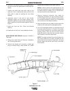
e. Be sure the cable is straight and then trim the liner
to the length shown in Figure 1 (a gauge is includ-
ed on the wrench provided with the connection kit
for gauging the cut-off length on 300 and 400 amp
gun tubes). Remove any burrs from the end of the
liner.
Figure 1
B-2B-2