


INSTALLATION
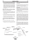
f. Screw the gas diffuser onto the end of the gun tube
and tighten with the wrench provided.
g. Tighten the set screw in the side of the gas diffuser
against the cable liner using the Allen wrench pro-
vided.
This screw should only be gently tightened.
Overtightening will split or collapse the liner and
cause poor wire feeding.
------------------------------------------------------------------------
h. Replace the nozzle insulator and gas nozzle.
INSTALLATION OF M18732 SERIES LINERS FOR
FEEDING ALUMINUM ELECTRODE
1. Lay the gun out straight on a flat surface and
remove the gas nozzle.
A. For all K466 except K466-3 and K466-4 connec-
tions, back out the set screw in the connector end
with a 5/64 (2.0 mm) Allen wrench.
B. For all K466-3 and K466-4 connections: Remove
the connector cap.
C. Back out the set screw in the diffuser for guns
that have a set screw in the diffuser.
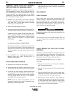
2. Remove the liner and insert a new untrimmed liner
into the connector end of the cable. Check that the
coils of the spring liner can be seen through the
holes in the gas diffuser.
A. For all K466-3 and K466-4 connections: If the
liner is going to be replaced with a different size
liner, loosen the set screw on the connector cap
and replace the liner material with the correct
size.
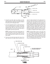
3. Mark the liner 3/16" (5 mm) from the end of the liner
guide or connector. Pull the liner partially out and
cut off the liner at the mark using a sharp knife.
4. Screw the brass liner nipple onto the liner and fully
seat the liner busing into the liner guide or the con-
nector.
A. For connector kits, except K466-3 and K466-4,
tighten the set screw in the cable connector.
B. For K466-3 and K466-4, screw in the connector
cap.
5. For guns with a diffuser set screw, tighten the set
screw in the side of the gas diffuser against the
cable liner using the Allen wrench provided.
This screw should only be gently tightened.
Overtightening will split or collapse the liner and
cause poor wire feeding.
------------------------------------------------------------------------
6. Replace the nozzle insulator and gas nozzle.
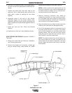
CONTACT TIP AND GAS NOZZLE INSTALLATION
a. Choose the correct size contact tip for the electrode
being used (wire size is stenciled on the side of the
contact tip) and screw it snugly into the gas diffuser.
b. Be sure the nozzle insulator is fully screwed onto
the gun tube and does not block the gas holes in the
diffuser. (NOTE: Insulator is not required when
using the optional fixed gas nozzles.)
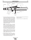
c. Slip the appropriate gas nozzle onto the nozzle
insulator. Adjustable gas nozzles are available with
a .62” (15.9 mm) or .50” (12.7 mm) I.D., and in both
standard (flush) and recessed design. The proper
nozzle should be selected based on the welding
application. Different length fixed nozzles are also
available to fit 300 and 400 amp gun tubes to allow
either spray or short-circuiting transfer welding.
Choose the gas nozzle as appropriate for the
GMAW process to be used. Typically, the contact tip
end should be flush to .12” (3.1 mm) extended for
the short-circuiting transfer process and .12” (3.1
mm) recessed for spray transfer. For the
Outershield (FCAW) process, 1/8” (3 mm) recess is
recommended.
CAUTION
MAGNUM 300 & 400
CAUTION
B-3B-3