


MAINTENANCE
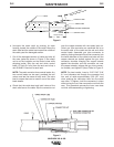
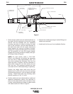
f. Check that the cable boot and cable handle are on
the cable. Slip the connector nut over the copper
strands with the threaded end out. Assemble
incoming connector to cable by forcing the steel
tube of the connector into the inside diameter of
the cable inner tube until the copper strands are
butted against the incoming connector shoulder.
Keeping the copper strands against the shoulder,
pull the connector nut over the copper strands,
engage the incoming connector threads, and tight-
en in place. Refer to Figure 3.
NOTE: For best results, insert a .219"/.240"
(5.6/6.1 mm) diameter rod through the connector
and into core of cable approximately 5.00” (127
mm) when pushing the connector tube into the
cable core tube. To tighten, hold the connector in
place while turning the nut. then remove the rod
from the core. This procedure ensures the inner
core does not kink while assembling or tightening.
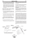
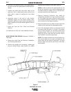
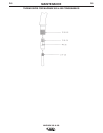
Position the plastic strain relief such that the
tapered end is 4.68 (119 mm) from the incoming
connector (see Figure 5). Lock into place with steel
housing. Plastic strain relief may overhang cable
jacket a maximum of .43" (11 mm).
g. Position cable boot and cable handle on cable and
assemble replacement control wire terminals in
place on the cable handle. Insert connector cover
in place. Install tailpiece and fasten to cable handle
with cable handle nut. Refer to Figure 5.
h. Replace the molded gas plug (or barbed fitting) and
feeder end connector.
j. Install and trim liner per Liner Installation Section.
MAGNUM 300 & 400
4.68
(119 mm)
.43 (11 mm)
MAX.
FEEDER END
CONNECTOR
PRESS HERE TO
REMOVE THE CABLE
HANDLE NUT
GAS PLUG
OR FITTING
CONNECTOR COVER
CABLE BOOT
CABLE
CABLE HANDLE
STRAIN RELIEF HOUSING
STRAIN RELIEF
INCOMING
CONNECTOR
TAIL PIECE
C
A
B
L
E
H
A
N
D
L
E
N
U
T
Figure 5
D-4D-4