


MAINTENANCE
e. Uncouple the strain relief by pushing its outer
housing toward the middle of the cable. Move the
strain relief and the cable boot toward the middle of
the cable, past the damaged section.
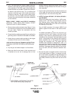
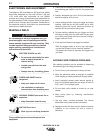
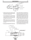
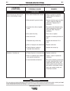
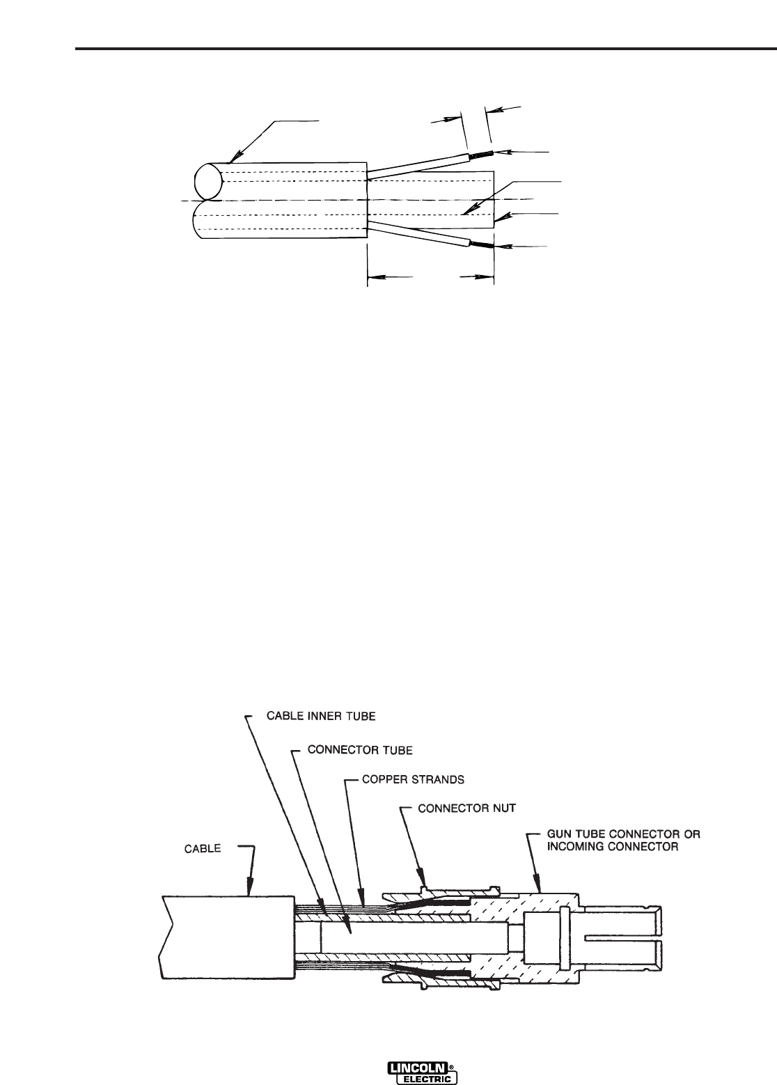
f. Cut off the damaged section of cable and strip off
the outer jacket as shown in Figure 2. Be careful
not to cut the insulation on the control wires while
stripping jacket. Strip the red and white control
leads 1/4 inch (6.4 mm) from the end and crimp a
new S19492-2 terminal to each lead.
NOTE: The cable contains three control leads. Any
two control leads can be used, provided the two
colors used are the same at both ends. The extra
lead is a spare that can be used if one of the other
leads breaks.
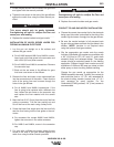
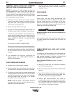
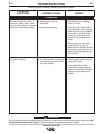
g. Check that the cable boot and both halves of the
strain relief are on the cable. Slip the connector nut
over the copper strands with the thread end out.
Orient gun tube connector so machined flat is on
the same side of the cable as the red and white
control leads. Assemble gun tube connector to
cable by forcing the steel tube of the connector into
the inside diameter of the cable inner tube until the
copper strands are butted against the gun tube
connector shoulder. Keeping the copper strands
against the shoulder, pull the connector nut over
the copper strands, engage the gun tube connec-
tor threads, and tighten in place. Refer to Figure 3.
NOTE: For best results, insert a .219”/.240” (5.6/
6.1 mm) diameter rod through the connector and
into core of cable approximately 5.00 (127 mm)
when pushing the connector tube into the cable
core tube. To tighten, hold the connector in place
while turning the nut, then remove the rod from the
core. This procedure ensures the inner core does
not kink while assembling or tightening.
MAGNUM 300 & 400
CABLE
CONTROL LEAD
INNER TUBE
COPPER STRANDING
CONTROL LEAD
1.65 (41.9 mm)
SKIN
.25" (6.4 mm) SKIN *
(BOTH CONTROL LEADS)
Figure 2
Figure 3
D-2D-2