


MAINTENANCE
h. Pull the cut-off lead terminals off the trigger assem-
bly and connect the replacement control lead ter-
minals.
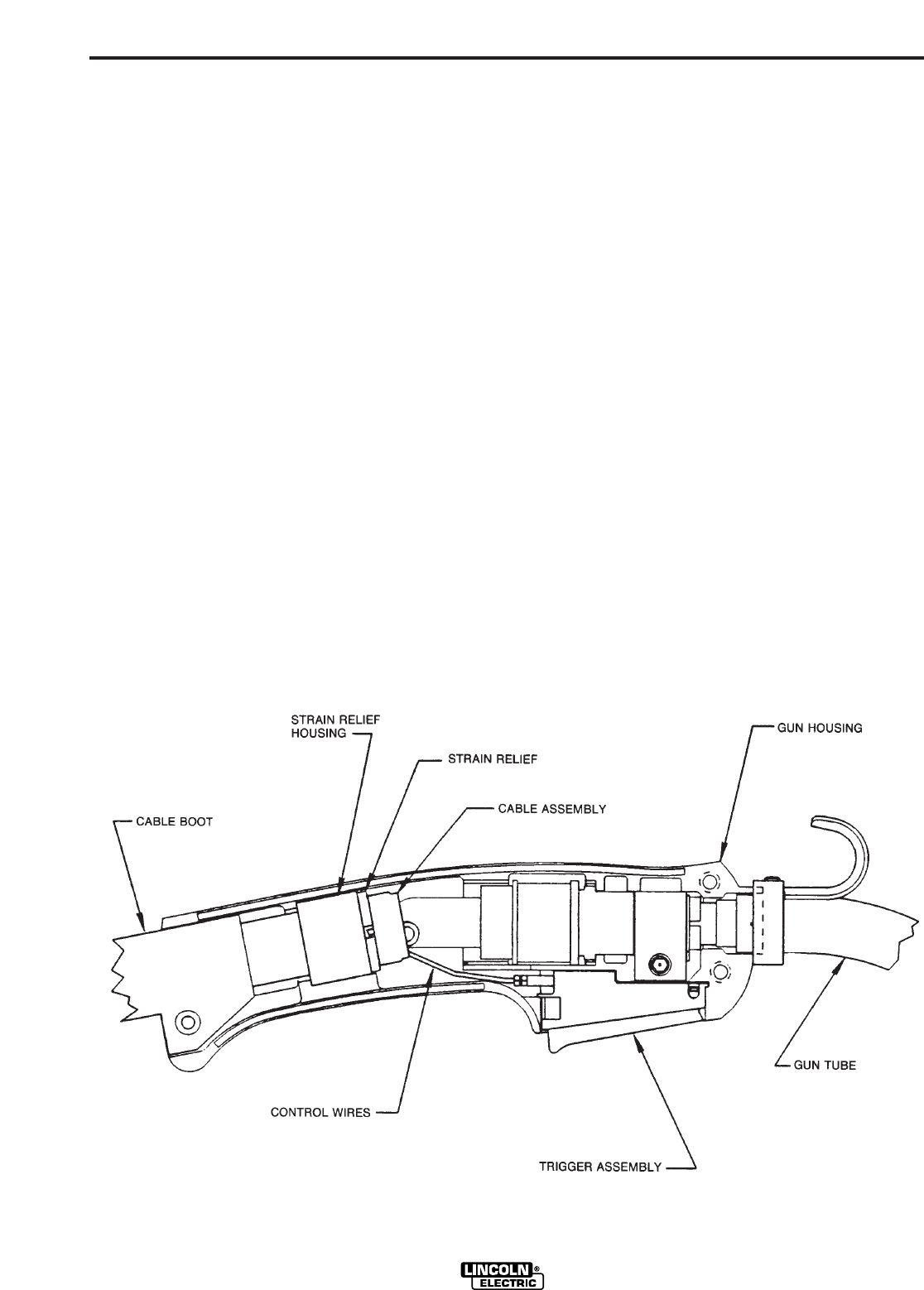
j. Position the cable boot and strain relief on the
cable so it fits in cable handle cavity and lock the
strain relief in place by pushing the two halves
together.
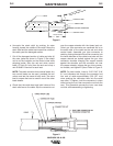
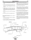
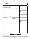
k. Assemble cable in left side of gun handle.
Assemble trigger into the proper handle cavity.
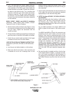
Assemble right side of gun handle and tighten the
three screws that hold the handle together. Refer to
Figure 4.
l. Install gun tube per Gun Tubes and Nozzles
Section.
m. Install and trim liner per Liner Installation Section.
WIRE FEEDER END REPAIR (Requires 2 S19492-1
Terminals)
a. Remove the cable liner per Removal, Installation,
and Trimming Instruction.
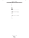
b. Remove the feeder end connector, molded gas
plug (or barbed fitting), cable handle nut, plastic
tailpiece and connector cover (see Figure 5).
NOTE: In order to remove the cable handle nut, the
tail of the connector cover must be depressed and
the cable handle nut rotated 1/4 turn counterclock-
wise as viewed from the feeder end.
c. Remove incoming connector from cable by
unscrewing connector nut from incoming connec-
tor. If the cable inner tube is difficult to remove from
the connector assembly, carefully slit it lengthwise
with a knife up to the brass connector.
d. Move the cable boot and cable handle toward the
middle of the cable past the damaged section.
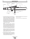
e. Cut off the damaged section of cable and strip off
the outer jacket as shown in Figure 2. Be careful
not to cut the insulation on the control wires while
stripping jacket. Strip the red and white control
leads 1/4 inch (6.4 mm) from the end and crimp a
new S19492-1 terminal to each lead.
NOTE: The cable contains three control leads. Any
two control leads can be used, provided the two
colors used are the same at both ends. The extra
lead is a spare that can be used if one of the other
leads breaks.
MAGNUM 300 & 400
Figure 4
D-3D-3