


E-4
TROUBLESHOOTING
E-4
SAM400 & 650
Observe all Safety Guidelines detailed throughout this manual
If for any reason you do not understand the test procedures or are unable to perform the tests/repairs safely, contact your Local
Lincoln Authorized Field Service Facility for technical troubleshooting assistance before you proceed.
CAUTION
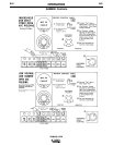
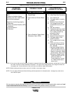
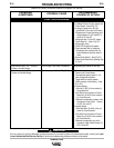
FUNCTION PROBLEMS
PROBLEMS
(SYMPTOMS)
POSSIBLE CAUSE
RECOMMENDED
COURSE OF ACTION
Output without control - one mode only
(Constant or Variable Voltage)
Output without control - both modes
(Constant and Variable Voltage)
SCR Bridge Test (See Procedure)
Continuity test. (Note B Pg. E-2).
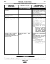
10. Voltage higher than 22 volts DC.
a) If between 22 and 100 volts, replace both
Control Boards. (Note A Pg. E-2).
b) If voltage is greater than 100 volts:
1)
Check diode D-4 for a short. See Procedure
2)Replace both Control Boards but only if
voltage between Pin #75 and #227 is
less than 100 volts DC.
11. Voltage less than 15 volts DC, replace
Control Board #1. (Note A Pg. E-2).
12. Voltage within limits.
a) Check SCR Bridge. See Procedure
b) Check generator field coil resistance.
1)Disconnect blue and brown field coil
leads. Resistance should be about 10
ohms.
c)
Replace Control Board #1. (Note A Pg. E-2).
d) Check Control Board #2 by following Step
2, Pg E-2.
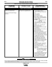
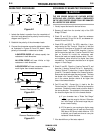
If bridge tests good proceed to next step.
1. Turn machine off.
2. Remove both Control Boards.
3. Place electrode polarity switch in con-
stant voltage positive position.
4. Toggle switch to mode in question.
5. Check continuity of the following (Note
B Pg. E-2):
a) Constant Voltage
1)Work to Pin #217 of the connector for
Control Board #2.
2)Pin #203 of the connector for Control
Board #2 to Pin #216 of the connector
for Control Board #1.
3)Between corresponding numbers of the
connectors for both Control Boards,
Pin #75, 216 and 227.
b) Variable Voltage
1)Blue field lead to Pin #201 of the con-
nector for Control Board #2.
2)Pin #202 of the connector for Control
Board #2 to Pin #216 of the connector
for Control Board #1.
3)Between corresponding pins of the
connectors of both Control Boards, Pin
#75, 216 and 227.