


E-5
TROUBLESHOOTING
E-5
SAM400 & 650
Observe all Safety Guidelines detailed throughout this manual
If for any reason you do not understand the test procedures or are unable to perform the tests/repairs safely, contact your Local
Lincoln Authorized Field Service Facility for technical troubleshooting assistance before you proceed.
CAUTION
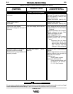
FUNCTION PROBLEMS
PROBLEMS
(SYMPTOMS)
POSSIBLE CAUSE
RECOMMENDED
COURSE OF ACTION
Output without control -
one mode
Output without control -
both modes
Output low in both modes -
open circuit voltage low (CV and VV
positions)
Arc difficult to start in CV position
using low current and voltage
(Characterized by large droplets, low
frequency transfer)
Continuity test. (Note B Pg. E-2).
Test rotor voltage (80-90 volts DC)
Test alternator outputs (22-24
volts DC)
1.Make continuity test outlined in Step 3,
on page E-2 except turn voltage con-
trol from maximum (0 ohms) to mini-
mum (10,000 ohms).
2.
Replace Control Board #2. (Note A Pg. E-2).
l. Replace Control Board #2
2.
Replace Control Board #1. (Note A Pg. E-2).
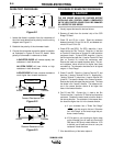
1.Rotor Voltage less than 80-90 volts DC
a)Check Diodes D1 - D2 - D5 -D6. See
Procedure.
b)Check SCR Bridge. See Procedure.
c)Check resistance of rotor fields.
Normal value about 14 ohms.
2.Rotor Voltage Within Limits
a)Check SCR Bridge. See Procedure.
b)Check generator field coil resis-
tance.
1)Disconnect blue and brown
field coil leads. Normal value
about 10 ohms. One field coil
open - 20 ohms. Both field
coils open - infinite resistance.
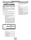
1.Set polarity switch in electrode positive
position.
2.Check voltage between work stud and
positive alternator lead connected to
input side of line contactor.
a)Within Limits
Check contactor contacts.
b)Less than 22-24 volts DC
Check three phase bridge recti-
fier diodes D7 - D8 -D9 -D10 -
D11 -D12. See Procedure.