


3
INSTALLATION
SQUARE WAVE TIG 175 PRO
3
b) A 3/4” (19mm) galvanized pipe or a 5/8” (16mm)
solid galvanized iron, steel or copper rod driven
at least eight feet into the ground.
The ground should be securely made and the ground-
ing cable should be as short as possible using cable of
the same size as the work cable, or larger. Grounding
to the building frame electrical conduit or a long pipe
system can result in re-radiation, effectively making
these members radiating antennas.
6. Keep cover and all screws securely in place.
7. Electrical conductors within 50 ft (15.2m) of the
welder should be enclosed in grounded rigid metal-
lic conduit or equivalent shielding, wherever possi-
ble. Flexible metallic conduit is generally not suit-
able.
8. When the welder is enclosed in a metal building, the
metal building should be connected to several good
earth driven electrical grounds (as in 5 (b) above)
around the periphery of the building.
Failure to observe these recommended installation
procedures can cause radio or TV and electronic
equipment interference problems and result in unsatis-
factory welding performance resulting from lost high
frequency power.
INPUT SUPPLY CONNECTIONS
Be sure the voltage, phase, and frequency of the input power
is as specified on the rating plate, located on the rear of the
machine.
1. Connect terminal marked to earth ground per National
Electric Code or any local codes.
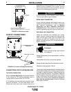
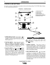
2. Connect the supply lines to the line switch studs as shown
in figure A.1.Use insulated barrel type terminals to fit #10-
32 studs.Torque each nut to 3.0 Nm.
3. Install in accordance with all local and national electrical
codes.
The Square Wave TIG is supplied with one cord connector.
The cord connector provides a strain relief for the input power
cord as it passes through the rear access hole.The cord con-
nector is designed for a cord diameter of 14.2 to 25.4 mm
(.560 to 1.00 in.). Strip away outer jacket of cord, trim fillers
and insert conductors mthrough cord connector. The jacket-
ed portion of the cord must go through the cord connector.
Tighten both connector screws.
INPUT RECONNECT PROCEDURE
On multiple input voltage welders, be sure the machine is
connected per the following instructions for the voltage being
supplied to the welder.
Failure to follow these instructions can cause immediate fail-
ure of components within the welder.
___________________________________________
Multiple voltage models are shipped connected for the high-
est voltage. To change this connection refer to the following
instructions.
For 220-240V connection (Refer to figure A.1):
1. Remove the sheet metal cover.
2.
Disconnect the copper link between the switch stud and H4.
3. Connect the copper link from the switch stud to H2 and
tighten nuts securely.
4. Replace sheet metal cover and all screws.
For 380V connection (Refer to figure A.1):
1. Remove the sheet metal cover.
2.
Disconnect the copper link between the switch stud and H4.
3. Connect the copper link from the switch stud to H3 and
tighten nuts securely.
4. Replace sheet metal cover and all screws.
For 400-415V connection (Refer to figure A.1):
1. Remove the sheet metal cover.
2.
Disconnect the copper link between the switch stud and H2 or H3.
3. Connect the copper link from the switch stud to H4 and
tighten nuts securely.
4. Replace sheet metal cover and all screws.
CAUTION
1
Also called “inverse time”or “thermal/magnetic” circuit breakers;circuit break-
ers which have a delay in tripping action that decreases as the magnitude of
the current increases.
WARNING
ELECTRIC SHOCK can kill.
• Turn the input power OFF at the
disconnect switch or fuse box
before working on this
equipment.
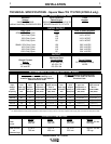
Refer to the
Technical Specifications
page at the beginning
of this section. Fuse the input circuit with the recommended
super lag fuses or delay type
1
circuit breakers. Using fuses
or circuit breakers smaller than recommended may result in
“nuisance” shut-offs from welder inrush currents even if not
welding at high currents.