


4
INSTALLATION
SQUARE WAVE TIG 175 PRO
4
Electrode/Gas Output Receptacle on the front of the
welder and turn it clockwise until it is tight. This is a
quick connect terminal and also provides the gas con-
nection for the shielding gas to the torch.
To avoid receiving a high frequency shock, keep the
TIG torch and cables in good condition.
__________________________________________
WORK CABLE CONNECTION
A work cable with attached work clamp is factory con-
nected to the Square Wave TIG 175 PRO. To minimize
high frequency interference, refer to
Machine
Grounding and High Frequency Interference
Protection
section of this manual for the proper pro-
cedure on grounding the work clamp and work piece.
SHIELDING GAS CONNECTION
Obtain the necessary inert shielding gas (usually
argon). Connect a cylinder of gas with a pressure reg-
ulator and flow gage. Install a gas hose between the
regulator and gas inlet (located on the rear of the
welder). The gas inlet has a 5/16-18 right hand female
thread; CGA #032.
The optional undercarriage features a pivoting platform
that simplifies loading and unloading of gas cylinders.
A cylinder is loaded by leaning it slightly sideways and
rolling it toward the platform. The cylinder’s weight will
push the platform downward against the floor, forming
a ramp. At this point, the cylinder may be rolled up the
platform into its final position. Secure the cylinder in
place with the provided chain. Unload by following
these steps in reverse.
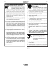
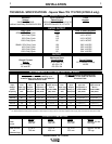
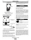
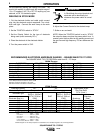
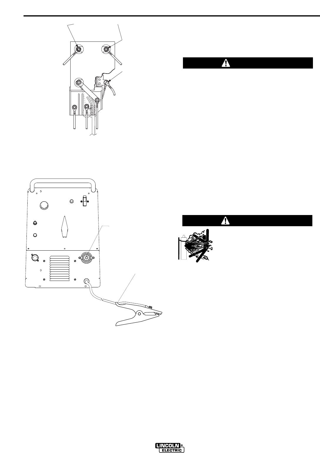
FIGURE A.1 Reconnect Leads
H2
INPUT SUPPLY
CONNECTION
H1
H3
H4
INPUT LEADS L1 & L2 USE
INSULATED BARREL RING
TERMINALS TO FIT #10-32
STUDS PROVIDED.
(DO NOT
REMOVE)
FOR 220-240V: CONNECT COPPER LINK TO H2
FOR 380V: CONNECT COPPER LINK TO H3
FOR 400-415V: CONNECT COPPER LINK TO H4 (AS SHOWN)
CYLINDER could explode
if damaged.
•Keep cylinder upright and chained
to a support.
•Keep cylinder away from areas where it could be
damaged.
•Never allow the torch to touch the cylinder.
•Keep cylinder away from live electrical circuits.
•Maximum inlet pressure 150 psi.
___________________________________________
WARNING
CONNECTIONS FOR TIG (GTAW) WELDING
TIG TORCH CONNECTION
Refer to
Included Equipment
in the Operation Section
of this manual for TIG welding equipment which is
included with the Square Wave TIG 175 PRO.
A TIG welding torch with cable and connector is sup-
plied with the welder. Turn the Power Switch “OFF”.
Connect the torch cable quick connect plug into the
WARNING
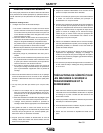
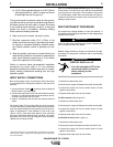
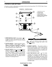
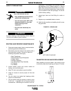
OUTPUT CONNECTIONS
FIGURE A.2 Location of Output Connections
ELECTRODE/GAS OUTLET
RECEPTACLE
WORK CABLE & CLAMP