


DC1123 QUICK START GUIDE
2
output voltages adjusted through I
2
C control from
600mv to 3.775V in 25mv increments.
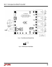
Q U ICK STA RT PROCEDU RE
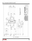
Using short tw isted pair leads for any pow er connec-
tions and w ith all loads and pow er supplies off, refer
to Figure 1 for the proper measurement and equip-
ment setup.
NOTE.
W hen measuring the input or output voltage ripple, care must be
taken to avoid a long ground lead on the oscilloscope probe. M easure the
input or output voltage ripple by touching the probe tip directly across the
VCC or VOUT and GND terminals. See Figure 2 for proper scope probe
technique.
1.
Place jumpers and load settings in the follow ing posi-
tions:
JP1 (RUN600A)
= ON
JP2 (RUN400A)
= ON
Load 1
= Consant Current 50mA
Load 2
= Constant Current 50mA
Load 3
= Constant Current 50mA
Load 4
= Constant Current 50mA
2.
Connect Pow er Supply PS1 to VIN terminals and ad-
just to 4.5 Volts to the demo board, as show n in Fig-
ure 1.
3.
Verify that OUT600A (1.8V) and OUT400A (1.5V) are
operational w ith proper output voltages.
4.
Once the proper output voltages are established, ad-
just the loads w ithin the operating range and observe
the output voltage regulation, ripple voltage, and effi-
ciency.
5.
Open the Quickstart Softw are as discribed in the
DC590 Quick Start Guide
6.
Set Jumpers JP1 (RUN400A) and JP2 (RUN600A) to
Off Position. Connect Ribbon cable from DC590 demo
circuit to J2. The LTC 3562 demonstation softw are
should pop-up automatically w hen the cable is in-
stalled.
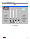
7.
Using the LTC3562 softw are GUI. See Figure 3. Set all
modes to Burst mode, VOUT 600A to 1.82V, VOUT
600B to 3.3V, VOUT 400A to 1.51V and VOUT 400B to
1.2V. Set all loads to 50mA. Check Auto Update but-
tons. Click on Enable All button.
8.
Once the proper output voltages are established, ad-
just the loads w ithin the operating range and observe
the output voltage regulation, ripple voltage, and effi-
ciency.
9.
Using the LTC3562 softw are GUI. Set all modes to
Pulse Skip mode, VOUT 600A to 1.82V, VOUT 600B to
3.3V, VOUT 400A to 1.51V and VOUT 400B to 1.2V.
Set all loads to 50mA.
10.
Once the proper output voltages are established, ad-
just the loads w ithin the operating range and observe
the output voltage regulation, ripple voltage, and effi-
ciency.
11.
Using the LTC3562 softw are GUI. Set all modes to
Forced Burst mode, VOUT 600A to 1.82V, VOUT 600B
to 3.3V, VOUT 400A to 1.51V and VOUT 400B to 1.2V.
Set all loads to 50mA.
12.
Once the proper output voltages are established, ad-
just the loads w ithin the operating range and observe
the output voltage regulation, ripple voltage, and effi-
ciency
13.
Using the LTC3562 softw are GUI. Set all modes to
LDO mode, VOUT 600A to 1.82V, VOUT 600B to 3.3V,
VOUT 400A to 1.51V and VOUT 400B to 1.2V. Set all
loads to 50mA.
14.
Once the proper output voltages are established, ad-
just the loads w ithin the operating range and observe
the output voltage regulation, ripple voltage, and effi-
ciency
15.
Using the LTC3562 softw are GUI. Set all modes to
Burst mode, VOUT 600A to 1.82V, VOUT 600B to
3.3V, VOUT 400A to 1.51V and VOUT 400B to 1.2V.
Set all loads to 50mA.
16.
M onitor POR600A pin w hile increasing Load1 until
the signal on POR600A goes low . The voltage on
P600A w ill be less than 92% of voltage setting.