


DC1123 QUICK START GUIDE
3
17.
Set Load1 and Load2 to 450mA. Set Load3 and
Load4 to 300mA. Adjust PS1 over the operating range
and observe line regulation.
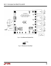
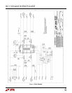
A PPL ICA TION INF ORM A TION
This demo circuit is designed to demonstrate the full
capability of the LTC3562 I
2
C Quad Synchronous
Step-Dow n DC-DC Regulator. Not all components are
required in all applications. The critical circuit com-
ponents are on the top of the board near the IC and
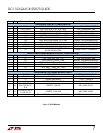
listed in the Required Circuit Components section of
the Bill of M aterials, in Figure 5.
The input capacitor netw ork of C1 and R1 is used to
dampen source lead inductances that commonly oc-
cur in laboratory setups w ith tw isted leads and a
bench pow er supply. W hen using a USB cable this
input damping netw ork w ill likely not be required.
Please note that the in-circuit capacitance of the
specified 10uF, 0805 ceramic capacitor for C1 and C2
is less than 5uF each w ith VIN greater than 4.25 Volts.
For good transient response and stability the output
capacitor each buck regulator should retain at least
4uF of capacitance over the operating temperature
and voltage range.
The output inductors for the OUT600A and OUT600B
are the recommended values of 3.3uH w hile the
OUT400A and OUT400B are 4.7uH.
Resistors R4 and R6 are to adjust the output voltage
seen on the OUT600A output w hile R3 and R4 w ill set
the voltage on the OUT400A output.