


3
Sending unit mounting plate configurations vary. When connecting the
EP-15, you will need whatever tools and supplies that will work with your
sending unit's specific design. Recommended tools include: pliers. If you
need to route the smart module or cable connector through a bulkhead,
you will need a drill and a 7/8" (22 mm) drill bit.
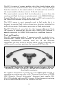
Supplies are not included, unless otherwise indicated. The EP-15's two
lead wires are pre-stripped. We recommend using marine-grade crimp-on
connectors that will fit your sending unit's electrical connections.
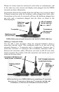
Installation
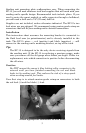
This instruction sheet assumes the mounting bracket is connected to
the fluid level arm (or potentiometer) and is already installed in the
tank. The EP-15 wires — red (positive) and black (negative) — will
connect to the sending unit's mounting bracket, on top of the tank.
Tip:
The EP-15 is designed to be the only device receiving signals from
the sending unit. If the EP-15 is replacing a previous gauge, make
sure you remove all the old gauge wires before you begin. If this is a
replacement, note which connection is positive before disconnecting
the old wires.
Caution:
Do NOT connect the sensor's blue locking collar connector to the
network until you have finished connecting the red and black
leads to the sending unit. This reduces the risk of a stray spark
when working around fuel tanks.
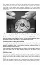
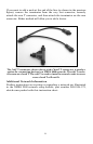
Your first step is to attach marine-grade crimp-on connectors to both
the red lead (+) and the black (–) lead.
Attach appropriate connectors to wire leads.