


7
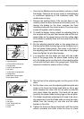
• Use only the Makita wrench provided to remove or install
the blades. Failure to do so may result in overtightening
or insufficient tightening of the installation bolts. This
could cause an injury.
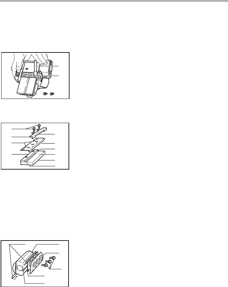
1. Remove the existing blade, if the tool has been in use,
carefully clean the drum surfaces and the drum cover. To
remove the blades on the drum, unscrew the three
installation bolts with the socket wrench. The drum cover
comes off together with the blades.
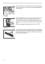
2. To install the blades, loosely attach the adjusting plate to
the set plate with the pan head screws and set the mini
planer blade on the gauge base so that the cutting edge
of the blade is perfectly flush with the inside flank of the
gauge plate.
3. Set the adjusting plate/set plate on the gauge base so
that the planer blade locating lugs on the set plate rest in
the mini planer blade groove, then press in the heel of
the adjusting plate flush with the back side of the gauge
base and tighten the pan head screws.
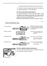
4. It is important that the blade sits flush with the inside
flank of the gauge plate, the planer blade locating lugs
sit in the blade groove and the heel of the adjusting plate
is flush with the back side of the gauge base. Check this
alignment carefully to ensure uniform cutting.
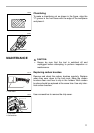
5. Slip the heel of the adjusting plate into the groove of the
drum.
6. Set the drum cover over the adjusting plate/set plate and
screw in the three hex flange head bolts so that a gap
exists between the drum and the set plate to slide the
mini planer blade into position. The blade will be posi-
tioned by the planer blade locating lugs on the set plate.
7. The blade’s lengthwise adjustment will need to be manu-
ally positioned so that the blade ends are clear and equi-
distant from the housing on one side and the metal
bracket on the other.
8. Tighten the three hex flange head bolts (with the socket
wrench provided) and hand rotate the drum to check
1. Socket wrench
2. Bolt
1. Pan head screw
2. Adjusting plate
3. Planer blade locating lugs
4. Gauge plate
5. Heel of adjusting plate
6. Set plate
7. Inside flank of gauge plate
8. Gauge base
9. Back side of gauge base
10.Mini planer blade
1
2
002564
1
2
3
4
5
6
7
8
9
10
002565
1. Mini planer blade
2. Groove
3. Set plate
4. Hex. flange head bolt
5. Drum plate
6. Drum
1
2
3
4
5
6
002566