


8
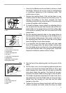
clearances between the blade ends and the tool body.
9. Check the three hex flange head bolts for final tightness.
10. Repeat procedures 1 - 9 for other blade.
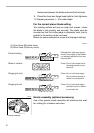
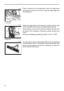
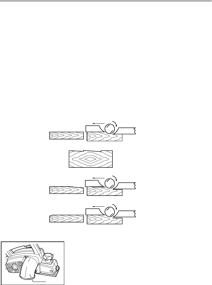
For the correct planer blade setting
Your planing surface will end up rough and uneven, unless
the blade is set properly and securely. The blade must be
mounted so that the cutting edge is absolutely level, that is,
parallel to the surface of the rear base.
Below are some examples of proper and improper settings.
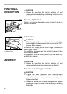
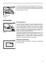
Nozzle assembly (optional accessory)
Use of the special nozzle assembly will minimize chip scat-
ter, making for a cleaner work area.
(A)
(B)
(B)
(A)
(B)
(A)
(A) Front base (Movable shoe)
(B) Rear base (Stationary shoe)
Correct setting
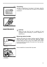
Nicks in surface
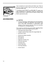
Gouging at start
Gouging at end
Although this side view cannot
show it, the edges of the blades
run perfectly parallel to the rear
base surface.
Cause: One or both blades fails to
have edge parallel to rear
base line.
Cause: One or both blade edges
fails to protrude enough in
relation to rear base line.
Cause: One or both blade edges
protrudes too far in relation
to rear base line.
EN0004-1
1. Nozzle assembly
1
002570