


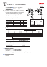
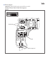

Wiring diagram
P 10/12
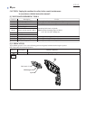
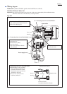
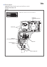
Fig. D-4
Route Lead wires
between these ribs.
Model 6411 (without Variable speed control and Reverse switch)
Machines With Choke Coil
Noise suppressor
[if used]
Important: Do not put slack portion of any Lead wire in the space surrounded by Field and Brush holders.
Otherwise Lead wires will be broken by rotating Armature.
Note: 1) Some countries do not use Noise suppressor.
2) Put Choke coils and Noise suppressor (if used) in place as illustrated in Fig. D-4.
Switch
Field
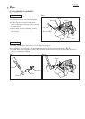
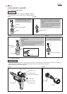
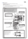
Connecting Lead wire to Brush holder
1) Brush holders are not reversible
when assembled to Housing (L).
Terminal insertion hole of each
Brush holder must be positioned
outside boss A/boss B.
2) Do not route each Lead wire
inside boss A/boss B.
boss A
Terminal
Brush holder
boss B
Brush holder
boss A
boss B
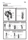
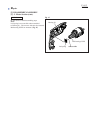
See "Connecting Lead wire to Brush holder".
See "Connecting Lead wire to Brush holder".
Put slack portion of Lead wire
in the space between Brush holder
and inside wall of Housing (L).
Otherwise the Lead wire will touch
rotating Armature.
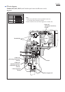
Fix two Lead wires
with this Lead wire holder.
Route Lead wires
under Brush holder.
Choke coil
(with orange Lead wires)
Choke coil
(with purple Lead wires)
Power supply cord
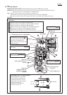
Choke coil lead wire (purple) to Brush holder
Choke coil lead wire (purple) to No.1a Terminal of Switch
Choke coil lead wire (orange) to Brush holder
Choke coil lead wire (orange) to Field
Field lead wire (black) to No.2a Terminal of Switch
Lead wires