


P 5 / 5
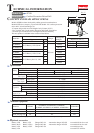
Circuit diagram
Wiring diagram
Color index of lead wires' sheath
Black
Red
Battery holder Switch D/C motor
Red marking
Red marking
Lead wire (red)
Lead wire (black)
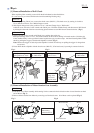
[1] Connecting Lead Wires with Motor
Connect the lead wires with the terminals on Motor so that they
are placed on the side of Housing (L). (Fig. 13)
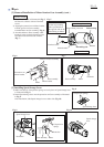
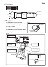
[2] Wiring in Housing
Route lead wires as illustrated in Fig. 14.
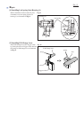
[3] Connecting Lead Wires with Battery Holder
Connect lead wires with the terminals on Battery holder as
illustrated in Fig. 15.
D/C Motor
Switch
Battery holder
Hold the lead wires with
lead wire holder.
Do not put lead wires on
this rib.
Lead wire (red)
Lead wire (black)
Fig. 13
Fig. 14
Fig. 15
Do not put lead wire (black)
on this rib.
Lead wire (red)
Lead wire (black)
Gear assembly
Route the lead
wire (red) through
the boss and the rib.
Route the lead
wire (black) through
the boss and the rib.