


5
CAUTION:
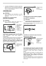
• Never actuate the shaft lock when the spindle is
moving. The tool may be damaged.
Press the shaft lock to prevent spindle rotation when
installing or removing accessories.
Switch action
CAUTION:
• Before plugging in the tool, always check to see
that the switch trigger actuates properly and returns
to the “OFF” position when released.
• Switch can be locked in “ON” position for ease of
operator comfort during extended use. Apply cau-
tion when locking tool in “ON” position and maintain
firm grasp on tool.
To start the tool, simply pull the switch trigger. Tool speed
is increased by increasing pressure on the switch trigger.
Release the switch trigger to stop.
For continuous operation, pull the switch trigger and then
push in the lock button.
To stop the tool from the locked position, pull the switch
trigger fully, then release it.
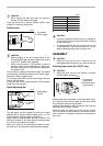
Speed adjusting dial
The tool speed can be changed by turning the speed
adjusting dial to a given number setting from 1 to 6. (At
the time when the switch trigger is fully pulled.)
Higher speed is obtained when the dial is turned in the
direction of number 6. And lower speed is obtained when
it is turned in the direction of number 1.
Refer to the table for the relationship between the num-
ber settings on the dial and the approximate tool speed.
CAUTION:
• If the tool is operated continuously at low speeds for
a long time, the motor will get overloaded, resulting
in tool malfunction.
• The speed adjusting dial can be turned only as far
as 6 and back to 1. Do not force it past 6 or 1, or the
speed adjusting function may no longer work.
ASSEMBLY
CAUTION:
• Always be sure that the tool is switched off and
unplugged before carrying out any work on the tool.
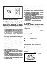
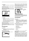
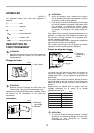
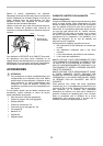
Installing loop handle (For 9227C only)
CAUTION:
• Always be sure that the loop handle is installed
securely before operation.
Always install the loop handle on the tool before opera-
tion. Hold the tool’s switch handle and the loop handle
firmly with both hands during operation.
Install the loop handle so that its protrusion will fit into the
matching hole in the gear housing.
Install the bolts and tighten them with the hex wrench.
The loop handle can be installed in two different direc-
tions as shown in the figures whichever is convenient for
your work.
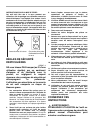
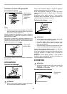
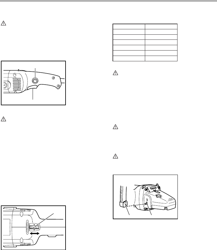
1. Lock button
2. Switch trigger
1. Speed adjust-
ing dial
1
2
003435
1
003440
1. Protrusion of
loop handle
2. Matching hole in
gear housing
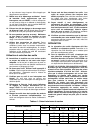
Number
1
2
3
4
5
6
min
-1
(
RPM
)
600
900
1,500
2,100
2,700
3,000
003441
12
003448