


P 4/ 8
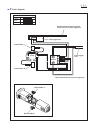
Repair
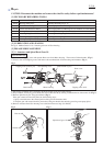
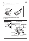
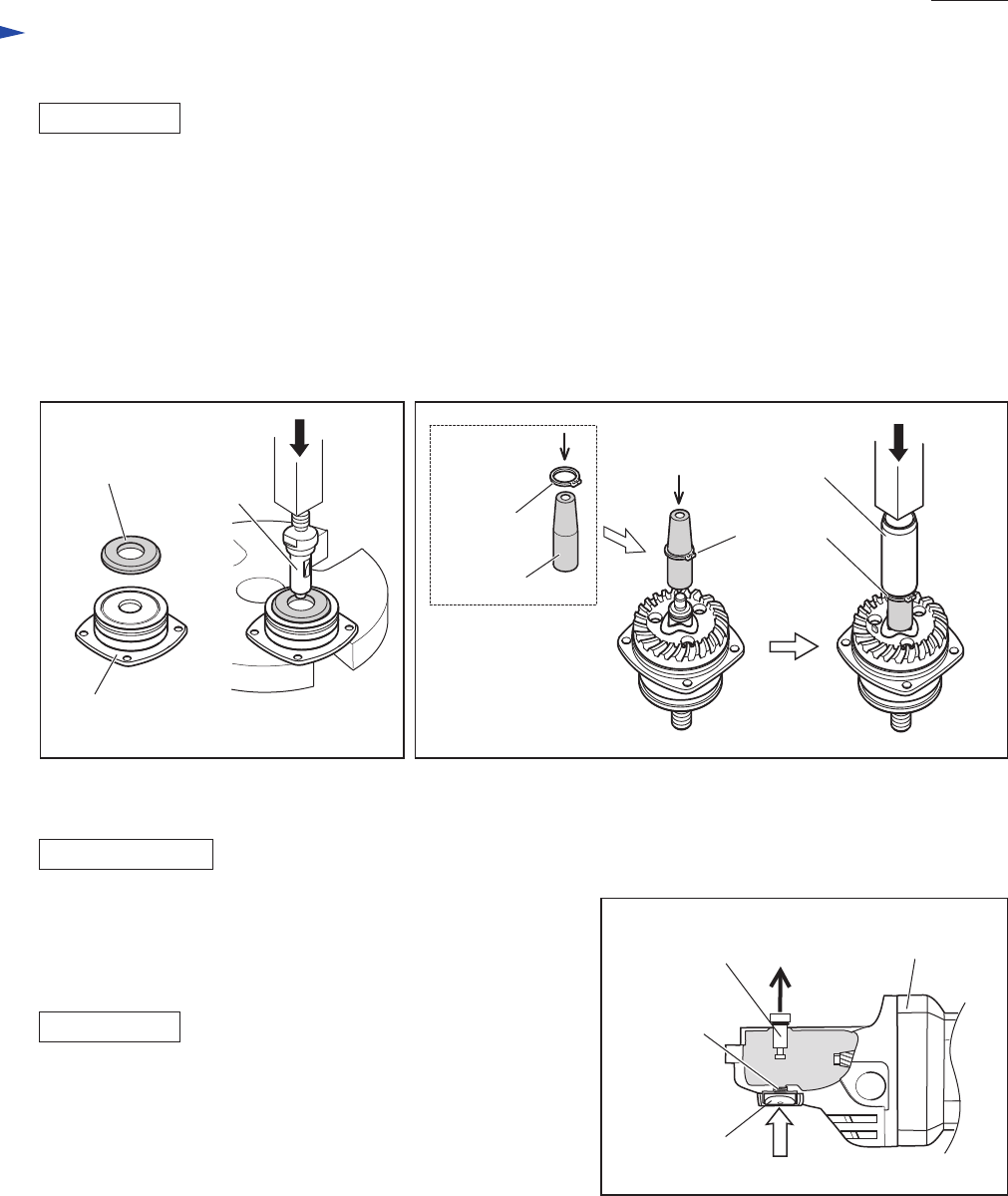
Fig. 9 Fig. 10
Do the reverse of the disassembling steps.
Important: Do not to forget to install Labyrinth ring because it is an important part that prevents dust from entering
into Bearing box. (Fig. 9)
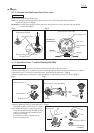
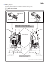
How to fit Retaining ring S-12 in place
See Fig. 10.
After installing Spiral bevel gear 37 and Wave washer 12 on Spindle;
1) Put Retaining ring S-12 on Retaining Ring Setting Jig (No.1R343) from the tapered end of the jig.
2) Put the jig onto Spindle, then put Bearing Setting Pipe 20-12.2 (No.1R028) over the jig.
3) Using arbor press, press down the pipe till the retaining ring is securely fitted in place on Spindle with a snap.
ASSEMBLING
ASSEMBLING
DISASSEMBLING
[3] -2. Spiral Bevel Gear 37 and Ball Bearing 6201DDW (cont.)
Spindle
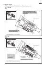
[3] -3. Disassembling/Assembling Shaft Lock Mechanism
[3] -4. Tightening Tapping Screws That Fasten the Field
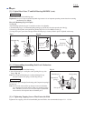
1) Remove Bearing box from Gear housing.
2) Pull off Shoulder pin 4 with pliers while pushing Pin cap with
finger. (Fig. 11)
Note: Do not pull off Shoulder pin 4 without holding Pin cap
because Compression spring 8 would sling Pin cap.
Push Shoulder pin 4 through Gear housing and Compression spring 8
into Pin cap.
Note: Do not reuse removed Pin cap because removal of Shoulder
pin 4 damages the inside surface of Pin cap, producing plastic
dust. Therefore, be sure to use a new Pin cap for replacement
and to remove all the plastic dust on Shoulder pin 4.
Fig. 11
Pin cap
Gear housing
Shoulder pin 4
Compression
spring 8
Tighten the two tapping screws that fasten Baffle plate and Field to the recommended torque of 1.1 - 1.3 Nm.
Labyrinth ring
No.1R343
Retaining
ring S-12
Retaining
ring S-12
No.1R028
Bearing box