


P 10/ 11
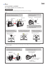
Wiring diagram
Fig. D-2
Fig. D-3
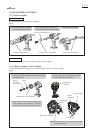
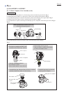
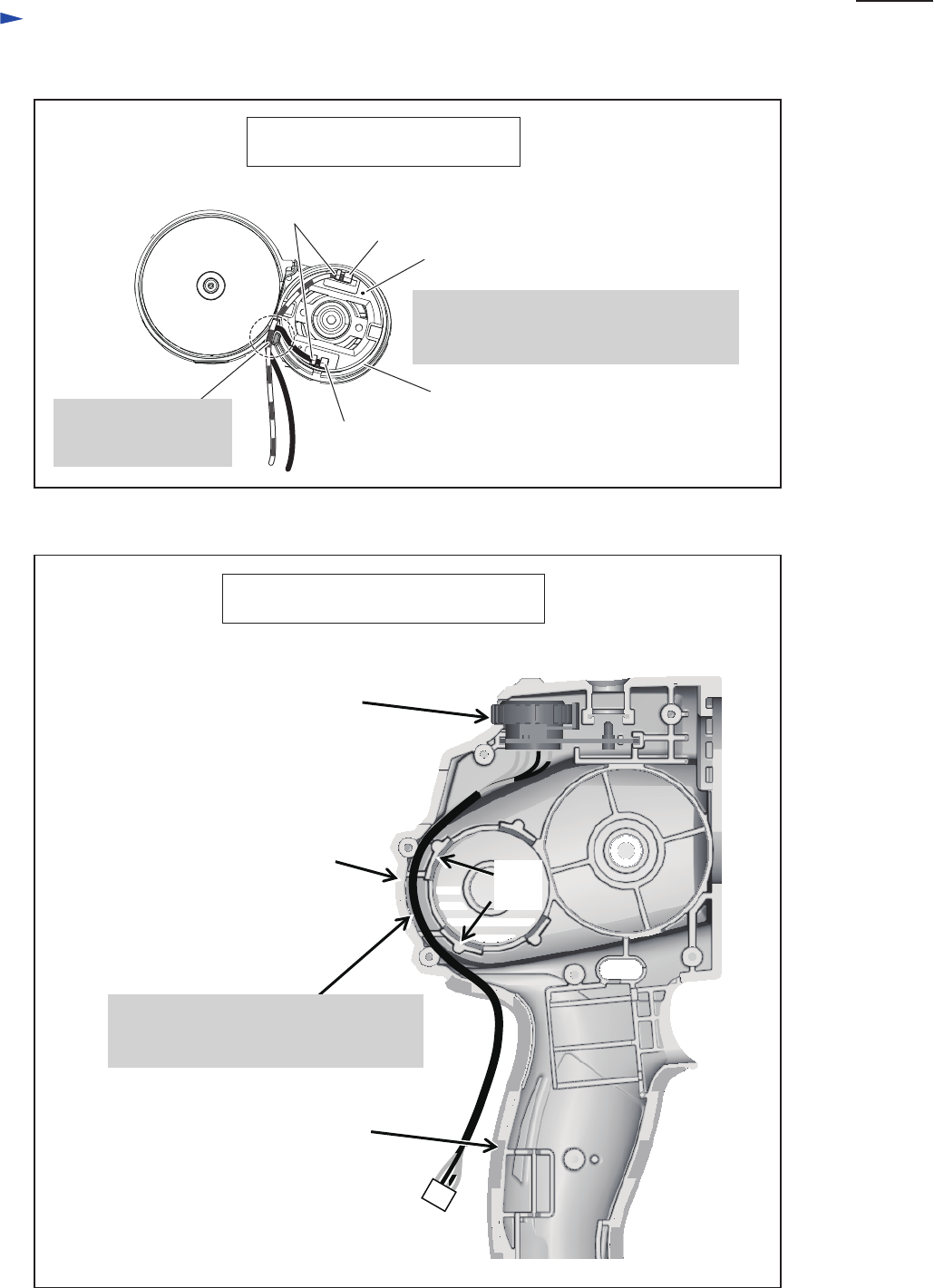
Wiring of Lead wires of Sub Controller
(Viewed from Housing (R) side)
Inner wall
Sub controller
リブ
Rib
Housing set (L)
Red point mark
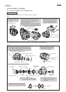
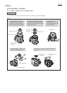
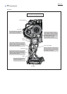
Wiring of DC motor’s Lead wires
Gear assembly
(Viewed from Housing (L) side)
Flag terminals have to be connected so that
their wire connecting portions are faced
toward Gear assembly side.
Wire connecting
portions
Flag terminal
Flag terminal
DC motor
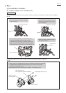
Lead wires have to be
fixed within Lead wire
holder.
Lead wires of Sub controller have to be
routed between Ribs and the inner wall of
Housing (L) complete.