


P 11/ 11
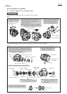
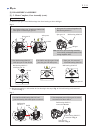
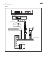
Wiring diagram
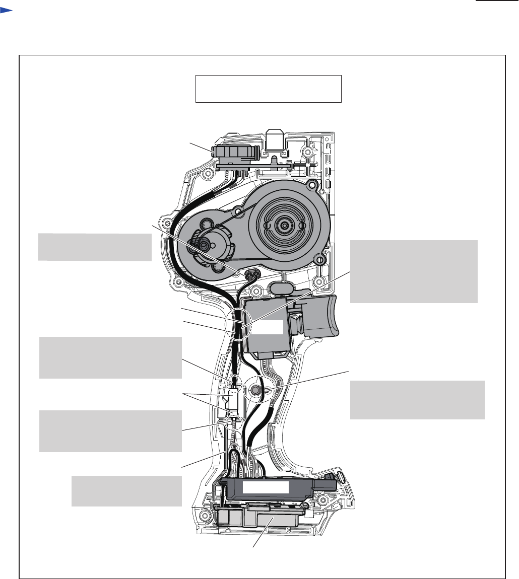
Fig. D-4
Wiring in Housing set (L)
(Viewed from Housing (R) side)
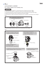
Sub controller
Line filter
Rib B
Rib A
Lead wire holder
Connector
Terminal
Switch
Rib C
Controller
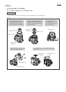
Route Sub controller’s lead wires
(black, white, red, blue) through
this Lead wire holder.
Route Sub controller’s lead wires
(black, white, red, blue) through
this Lead wire holder.
Do not route Connector’s
lead wires on Rib C.
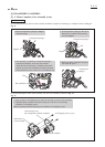
Route Controller’s lead wires to
DC Motor (black, red) through
this Lead wire holder.
Put Line filter in this place.
(when using Line filter)
Route Sub controller’s lead
wires (black, white, red, blue)
and Controller’s lead wires to
DC Motor (black, red)
between Ribs A and B.