


P 13/ 15
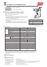
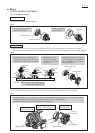
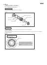
Circuit diagram
Fig. D-4
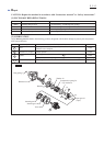
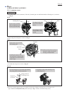
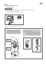
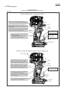
Wiring diagram
Fig. D-5
BTW074, BTW104
(equipped with Automatic Impact Stop System)
Yellow
Brush holder complete
Brush holder
Line filter*
*Line filter is not used for some countries.
Switch
LED Light
Circuit
LED Circuit
(Warning of Power Reduce)
LED Warning
Light
Controller
Connector
(6 pin)
Connector
(4 pin)
Terminal
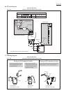
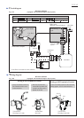
Color index of lead wires' sheath
Black
Blue
Red
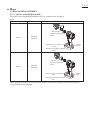
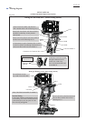
BTW074, BTW104
(equipped with Automatic Impact Stop System)
Green
Gray
White
Orange
Wiring to M1 Terminal of Switch
Wiring to M2 Terminal of Switch
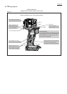
Viewed from
Housing set (L) side
Viewed from
Housing set (R) side
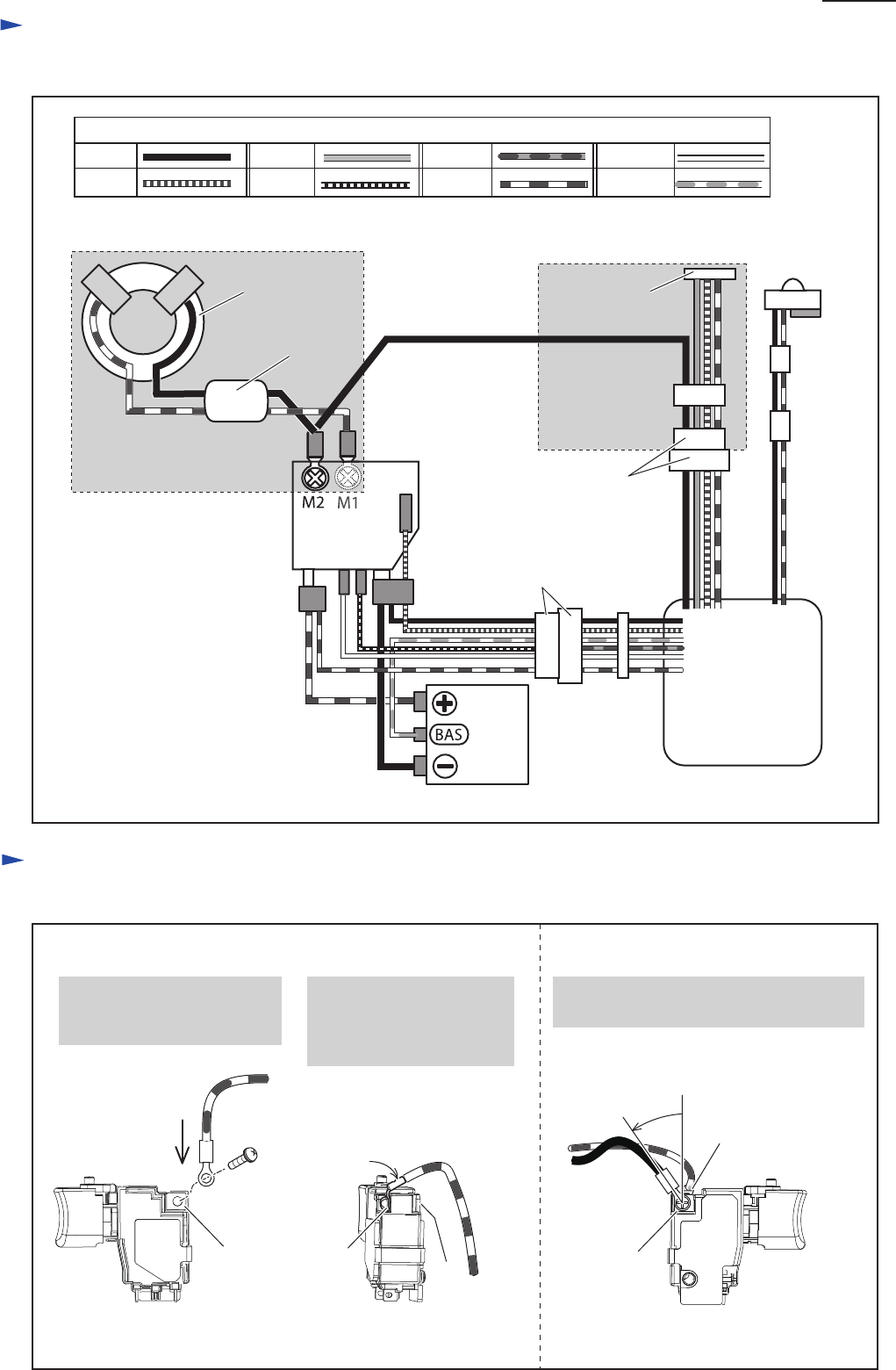
Viewed from
Rear side
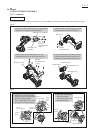
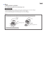
M1
M1
M2
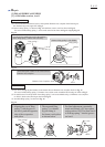
M1
30°±5º
M2
2. Bend the Terminal 90º
toward M2 Terminal side
so that Line filter can be
placed on Switch.
1. Secure Insulated terminal to
M1 Terminal with a screw
as shown below.
Secure Insulated terminal to M2 Terminal
tilting approx. 30º±5º as shown below.