


P 15/ 15
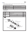
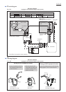
Wiring diagram
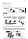
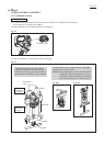
Fig. D-7
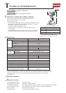
BTW074, BTW104
(equipped with Automatic Impact Stop System)
Line filter
Route Line filter
between Ribs E and F.
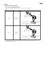
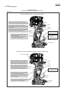
Wiring in Housing set (L) (after setting Switch)
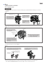
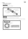
Rib F
LED light
Switch
Rib E
Route Lead wires for connecting
to Switch between Boss and
the inner wall of Housing set (L).
Boss
Be careful not to route
any Lead wires on this Rib.
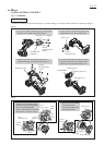
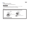
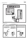
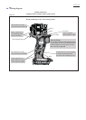
Route Lead wires of
LED warning lamp
between the Ribs.
Secure lead wires of
both Connectors (6 pin)
with Lead wire holders.
LED warning lamp
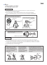
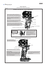
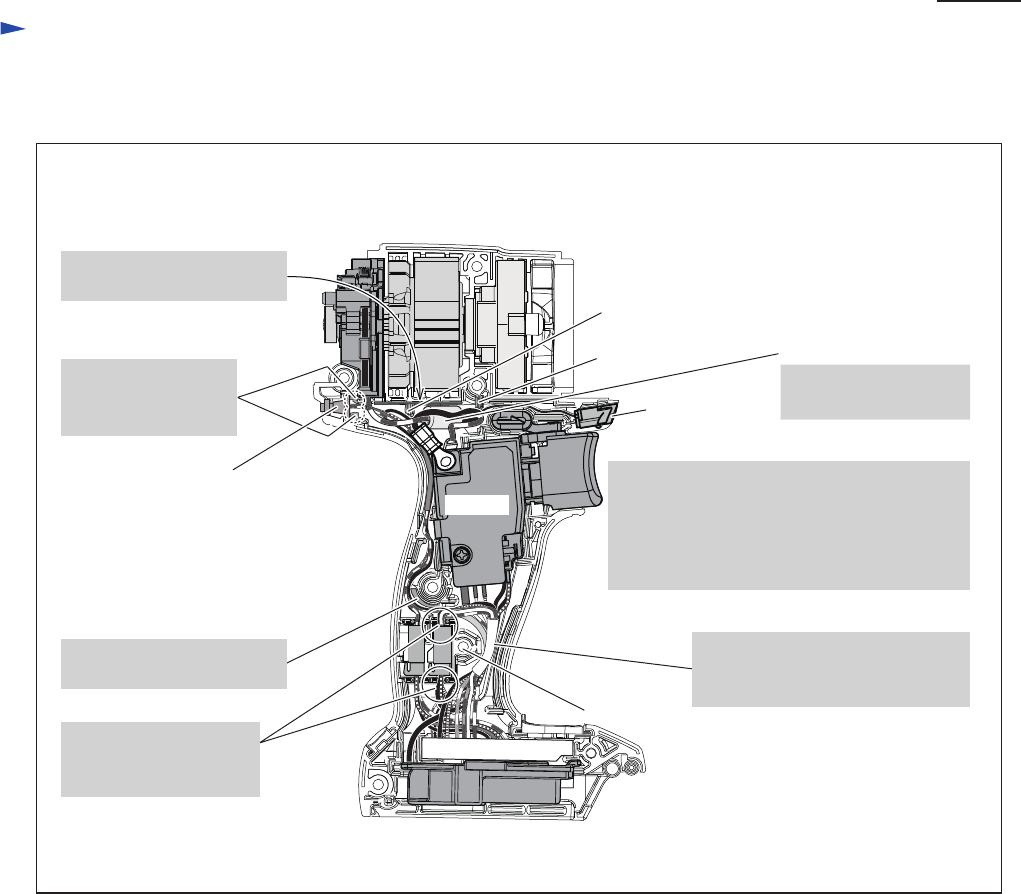
Note for Wiring:
If Line filter interferes with Housing set (R)
in assembling, check that Insulated terminal
is tilted enough to save the space for Line
filter referring to Fig. D-5.
Be careful not to route
any Lead wires on this Rib.