


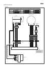
Wiring diagram
P 9
/ 11
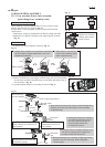
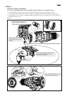
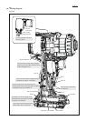
Fig. D-3
Boss A
Boss B
Controller
Capacitor of Controller
Rib of Controller
Terminal
Rib C
Rib E
Rib E
Rib D
Stator complete
The slack of Lead wire (Red) from
Terminal must not be piled on/under
Capacitor of Controller.
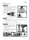
Do not put any lead wires
on these ribs.
Thick lead wires from Stator complete
must be put on the other thin lead wires
for the designated area .
Lead wires from Stator complete must be
routed between Boss A and Rib C.
Lead wire (Red) from Terminal must be;
• placed under Lead wires from Stator complete
• routed between Rib D and Rib E.
Lead wires from Terminal must be
placed under Rib of Controller.
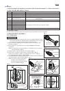
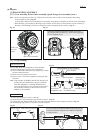
Flag terminal
Switch
Lead wire
(white)
Set Flag terminal to Switch
as shown above.