


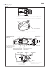

Fig. D-2
hook of Controller
Terminal
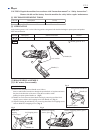
Motor housing L Switch unit (large) Route LED lead wires
between ribs.
Route Lead wires between
emboss and rib.
Route Lead wires between
Switch unit (large) and rib.
emboss
Connector LEDrib ribsrib
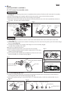
Route this Lead wire (red) through the hook of Controller.
Fix Switch unit (microswitch/ green color) to Gear case as illustrated above.
Handle (L)
Do not put Lead wires
on ribs and emboss.
Do not pinch Lead wires between
Handle and Motor housing.
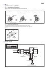
Fix Controller lead wires
(red, black) in lead wire
holder here.
Put Controller lead wires
(signal path) in the groove
on Housing L here.
Switch unit (microswitch/ green color)Gear case
Controller
Motor housingterminal for battery
Wiring diagram
P 5/ 5