


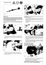
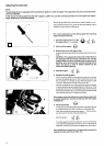
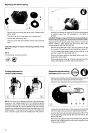
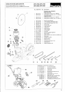
Replacing the return spring
~~
-
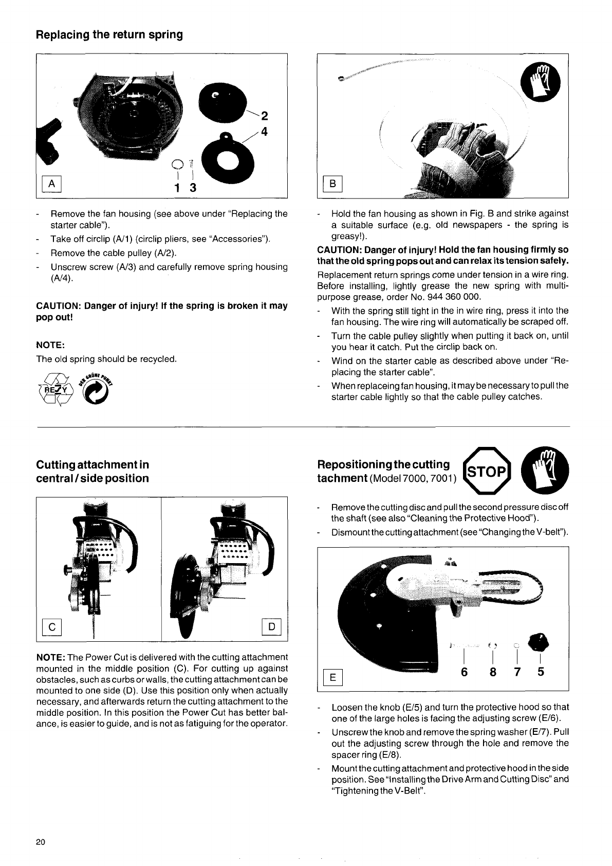
Remove the fan housing (see above under “Replacing the
starter cable”).
Take off circlip
(N1)
(circlip pliers, see “Accessories”).
Remove the cable pulley
(A/2).
Unscrew screw (A/3) and carefully remove spring housing
-
-
-
W4).
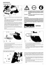
CAUTION: Danger of injury! If the spring is broken it may
pop out!
NOTE:
The old spring should be recycled.
-
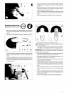
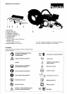
Hold the fan housing as shown in Fig. B and strike against
a suitable surface (e.g. old newspapers
-
the spring is
greasy!).
CAUTION: Danger
of
injury! Hold the fan housing firmly
so
that the old spring pops out and can relax its tension safely.
Replacement return springs come under tension in a wire ring.
Before installing, lightly grease the new spring with multi-
purpose grease, order
No.
944
360
000.
-
With the spring still tight in the in wire ring, press it into the
fan housing. The wire ring will automatically be scraped off.
Turn the cable pulley slightly when putting it back on, until
you hear it catch. Put the circlip back on.
Wind on the starter cable as described above under “Re-
placing the starter cable”.
When replaceingfan housing, it may be necessaryto pull the
starter cable lightly
so
that the cable pulley catches.
-
-
-
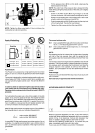
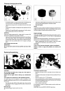
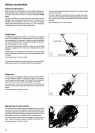
Cutting attachment in
central /side position
NOTE:
The Power Cut is delivered with the cutting attachment
mounted in the middle position
(C).
For cutting up against
obstacles, such as curbs orwalls, the cutting attachment can be
mounted to one side
(D).
Use this position only when actually
necessary, and afterwards return the cutting attachment to the
middle position. In this position the Power Cut has better bal-
ance, is easier to guide, and is not as fatiguing for the operator.
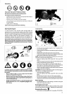
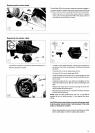
Repositioning the cutting
tachment
(Model
7000,7001)
-
Remove the cutting disc and pull the second pressure disc off
the shaft (see also “Cleaning the Protective
Hood).
Dismountthe cutting attachment (seel‘changing theV-belt”).
-
-
Loosen the knob
(E/5)
and turn the protective hood
so
that
one of the large holes is facing the adjusting screw (E/6).
Unscrew the knob and remove the spring washer (E/7).
Pull
out the adjusting screw through the hole and remove the
spacer ring (E/8).
Mount the cutting attachment and protective hood in the side
position. See “installing the Drive Arm and Cutting Disc” and
“Tightening the V-Belt”.
-
-
20