


7
ASSEMBLY
CAUTION:
• Always be sure that the tool is switched off and
unplugged before carrying out any work on the tool.
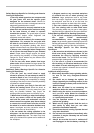
Installing side grip (handle)
CAUTION:
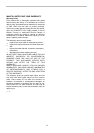
• Always be sure that the side grip is installed
securely before operation.
010807
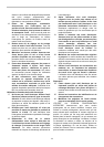
Screw the side grip securely on the position of the tool as
shown in the figure.
Installing or removing wheel guard (For
depressed center wheel , multi disc / abrasive
cut-off wheel , diamond wheel)
CAUTION:
• When using a depressed center grinding
wheel/Multi-disc, flex wheel, wire wheel brush, or
cut-off wheel, the wheel guard must be fitted on the
tool so that the closed side of the guard always
points toward the operator.
• Use a wheel guard with a specific shape according
to the application.
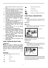
For tool with locking screw type wheel guard
1
2
3
010692
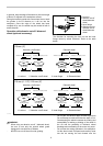
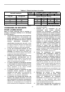
Mount the wheel guard with the protrusion on the wheel
guard band aligned with the notch on the bearing box.
Then rotate the wheel guard to such an angle that it can
protect the operator according to work. Be sure to tighten
the screw securely.
To remove wheel guard, follow the installation procedure
in reverse.
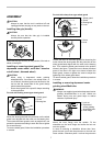
For tool with clamp lever type wheel guard
1
2
3
4
010697
1
2
009431
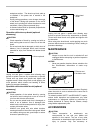
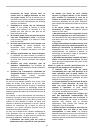
Loosen the lever on the wheel guard after loosening the
screw. Mount the wheel guard with the protrusion on the
wheel guard band aligned with the notch on the bearing
box. Then rotate the wheel guard around to the position
shown in the figure. Tighten the lever to fasten the wheel
guard. If the lever is too tight or too loose to fasten the
wheel guard, loosen or tighten the screw to adjust the
tightening of the wheel guard band.
To remove wheel guard, follow the installation procedure
in reverse.
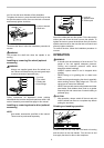
Installing or removing depressed center
grinding wheel/Multi-disc
WARNING:
• Always use supplied guard when depressed center
grinding wheel/Multi-disc is on tool. Wheel can
shatter during use and guard helps to reduce
chances of personal injury.
1
2
3
010693
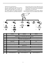
Mount the inner flange onto the spindle. Fit the
wheel/disc on the inner flange and screw the lock nut
onto the spindle.
In case of mounting a wheel/disc thinner than 3mm,
place the lock nut so that the protrusion on the lock nut
faces outside. Otherwise place it so that the protrusion
1. Lock nut
2. Depressed
center grinding
wheel/Multi-disc
3. Inner flange
1. Screw
2. Lever
1. Wheel guard
2. Screw
3. Bearing box
4. Lever
1. Wheel guard
2. Screw
3. Bearing box