


P 8/ 13
Repair
[3] DISASSEMBLY/ASSEMBLY
[3] -3. Switch mechanism (Switch lever and Switch knob)
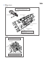
DISASSEMBLING
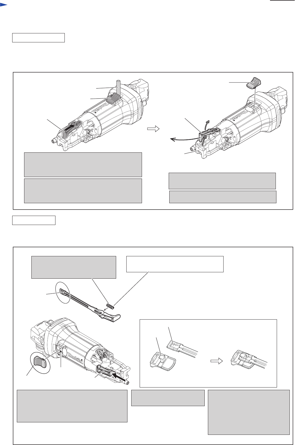
ASSEMBLING
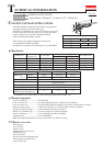
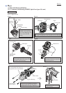
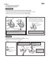
(1) Remove Rear cover from Motor housing by removing 4x18 Tapping screw. (Fig. 2)
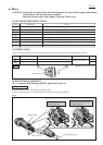
(2) Switch lever and Switch knob can be disassembled from the machine as illustrated in Fig. 26.
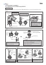
1R 281
Switch knob
1. While locking Switch knob with 1R281,
strongly push Switch lever in a direction
designated with black arrow.
2. Switch lever is disconnected from the locking
claw of Switch knob.
And Switch knob can be removed.
Switch Lever
4. Pull out Switch lever from Motor housing.
3. Bend Switch lever to make it free from
the wall of Switch box.
Fig. 26
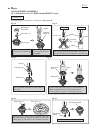
Fig. 27
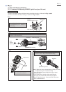
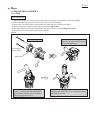
1. Make sure that Compression
spring 4 is assembled to Switch
lever in advance.
Compression spring 4 for pushing back
Switch lever to OFF position
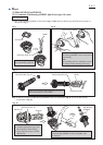
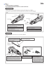
3. Fit the hook of Swtich knob
to the hole of Switch knob.
2. Push Switch lever into Motor housing
until the hole of Switch lever comes into
sight through Switch knob assembling hole
on Motor housing. And keep the position.
hole for
hook of
Switch lever
hook
Interlock Switch knob with Switch lever as illustrated in Fig. 27.
Switch
lever
Switch knob
the reverse side of
Switch knob
Switch lever
wall of
Switch box
Switch knob
hole
the top end of
Switch lever
4. Release Switch lever.
(The hook of Switch knob
interlocks with the hole of
Switch lever when Switch lever
is pushed back to OFF position
by Compression spring 4.)
Switch knob
assembling
hole