


P 9/ 13
Repair
[3] DISASSEMBLY/ASSEMBLY
[3] -4 Shaft Lock Mechanism
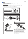
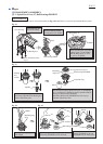
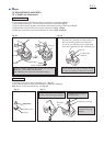
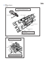
DISASSEMBLING
Applying 1R268 to Shoulder pin 4 through the small hole
on Pin cap, strike 1R268 with Hammer.
Now, Shoulder pin 4 comes out from Gear housing.
Release 1R268 from Pin cap carefully so that
Pin cap is not slung by Compression spring 8.
Shoulder Pin 4
O ring 5
Pin cap
Note: Do not removed Pin cap because removal of
Shoulder pin 4 damages the inside surface of
Pin cap, producing plastic dust. Therefore,
be sure to use a new Pin cap for replacement
and remove all the plastic dust on Should pin 4.
Pin cap
Pin cap
Compression
spring 8
1R268
1R350
Fig. 28 Fig. 29
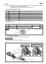
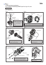
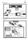
(1) Disconnect Carbon brush from Armature’s commutator as illustrated in Fig. 2.
(2) Disassemble Bearing box section from Gear housing as illustrated in Fig. 3.
(3) Separate Gear housing together with Armature from Motor housing as illustrated in Fig. 4.
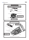
(4) Disassemble Armature from Gear housing as illustrated in Figs. 5 and 6.
(5) Shaft lock mechanism can be disassembled in the order of Figs. 28 and 29.
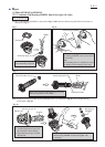
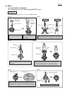
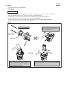
ASSEMBLING
Fig. 30
Fig. 31
(1) Remove all the plastic dust on Shoulder pin 4. (Fig. 30)
(2) Assemble the parts for Shaft lock mechanism as illustrated in Fig. 31.
Note: Do not use the removed Pin cap. (See Fig. 29)
plastic dust
O ring 5
Shoulder pin 4
Shoulder
pin 4
Install Pin cap by pressing it
to Shoulder pin 4.
Insert Shoulder pin 4 through
the hole of Gear housing complete.
Pin cap
Do not forget to set
Compression spring 8
in place.
Compression spring 8