


6
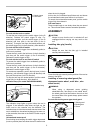
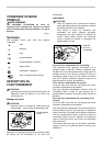
Mount the wheel guard with the protrusion on the wheel
guard band aligned with the notch on the bearing box.
Then rotate the wheel guard around 180 degrees
counterclockwise. Be sure to tighten the screw securely.
To remove wheel guard, follow the installation procedure
in reverse.
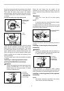
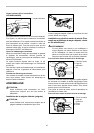
For tool with clamp lever type wheel guard
1
2
3
4
010644
1
2
010645
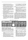
Loosen the lever on the wheel guard. Mount the wheel
guard with the protrusion on the wheel guard band
aligned with the notch on the bearing box. Then rotate
the wheel guard around to the position shown in the
figure. Tighten the lever to fasten the wheel guard. If the
lever is too tight or too loose to fasten the wheel guard,
loosen or tighten the nut to adjust the tightening of the
wheel guard band.
To remove wheel guard, follow the installation procedure
in reverse.
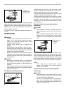
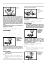
Installing or removing depressed center
grinding wheel/Multi-disc (accessory)
WARNING:
• Always use supplied guard when depressed center
grinding wheel/Multi-disc is on tool. Wheel can
shatter during use and guard helps to reduce
chances of personal injury.
1
2
3
010656
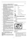
Mount the inner flange onto the spindle. Fit the
wheel/disc on the inner flange and screw the lock nut
with its protrusion facing downward (facing toward the
wheel).
WARNING:
• Never use a more than 6.5 mm thick grinding
wheel.
NOTE:
• In countries other than United States and Canada,
Inner flange 45 can be also used.
To tighten the lock nut, press the shaft lock firmly so that
the spindle cannot revolve, then use the lock nut wrench
and securely tighten clockwise.
1
2
010647
To remove the wheel, follow the installation procedure in
reverse.
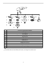
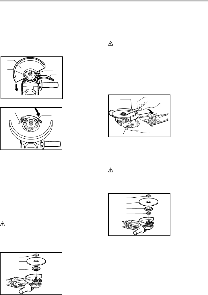
Installing or removing flex wheel (optional
accessory)
WARNING:
• Always use supplied guard when flex wheel is on
tool. Wheel can shatter during use and guard helps
to reduce chances of personal injury.
1
2
3
4
010657
Follow instructions for depressed center grinding
wheel/Multi-disc but also use plastic pad over wheel. See
order of assembly on accessories page in this manual.
Installing or removing abrasive disc (optional
accessory)
NOTE:
• Use sander accessories specified in this manual.
These must be purchased separately.
1. Lock nut
2. Flex wheel
3. Plastic pad
4. Inner flange
1. Lock nut wrench
2. Shaft lock
1. Lock nut
2. Depressed
center grinding
wheel/Multi-disc
3. Inner flange
1. Nut
2. Lever
1. Wheel guard
2. Bearing box
3. Nut
4. Lever