P 7/ 17
Repair
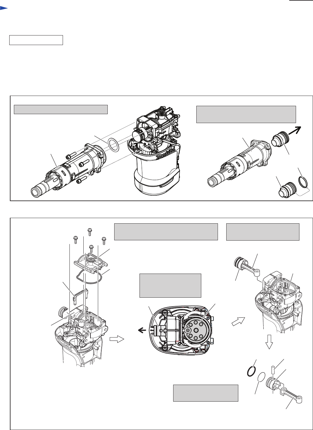
Fig. 15
Fig. 16
DISASSEMBLING
[3] DISASSEMBLY/ASSEMBLY
[3]-4 Piston, Striker, Cylinder
Remove Barrel from Crank housing
M6x25 Hex socket
head bolt (4pcs.)
(1) Disassemble Chuck section as illustrated in Figs 2, 3 and 4.
(2) Remove Housing cover as illustrated in Fig. 9. In case of HM0871C, disassemble Active dynamic vibration absorber as
illustrated Figs. 9 and 10.
(3) Striker and Piston can be disassembled as illustrated in Figs. 15 and 16.
Note: It is not necessay to remove Tool holder from Barrel.
Barrel
Crank cap
Remove Crank cap, Seal ring, Air pipe
and Flat washer 34 from Crank housing.
O rings on Piston can be
replaced .
Seal ring
Flat washer 34
Air pipe
Turning Crank shaft,
set Piston to the closest
position to Barrel side.
Barrel
Striker
O ring 24
Striker
Separate Striker from Barrel, and then
remove O ring 24 from Striker.
M4x18 Pan
head screw (4pcs.)
Crank housing
O ring 24
Piston
Piston
Pin 8
O ring 26
Connecting rod
Connecting rod
Crank
shaft
And remove Piston together
with Connecting rod.
Barrel
side
Piston
Crank shaft
Note: Do not lose Flat washer 34 between
Crank housing and Barrel.


