


P 11/ 13
Repair
ASSEMBLING
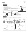
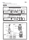
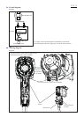
Fig. 25
(1) Pressfit Ball bearing 608ZZ into Bearing box.
(2) Put Clutch cam B, Swash bearing 10, Flat washer 8 and Bearing box to Spur gear 10 in order,
then secure them using 1R033, 1R026 and arbor press.
(3) Fit Bearing retainer in Bearing box, then pressfit Helical gear 26 to the shaft of Swash bearing section.
Be careful of the directions of Bearing box and Helical gear 26. (Fig.25)
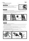
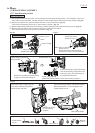
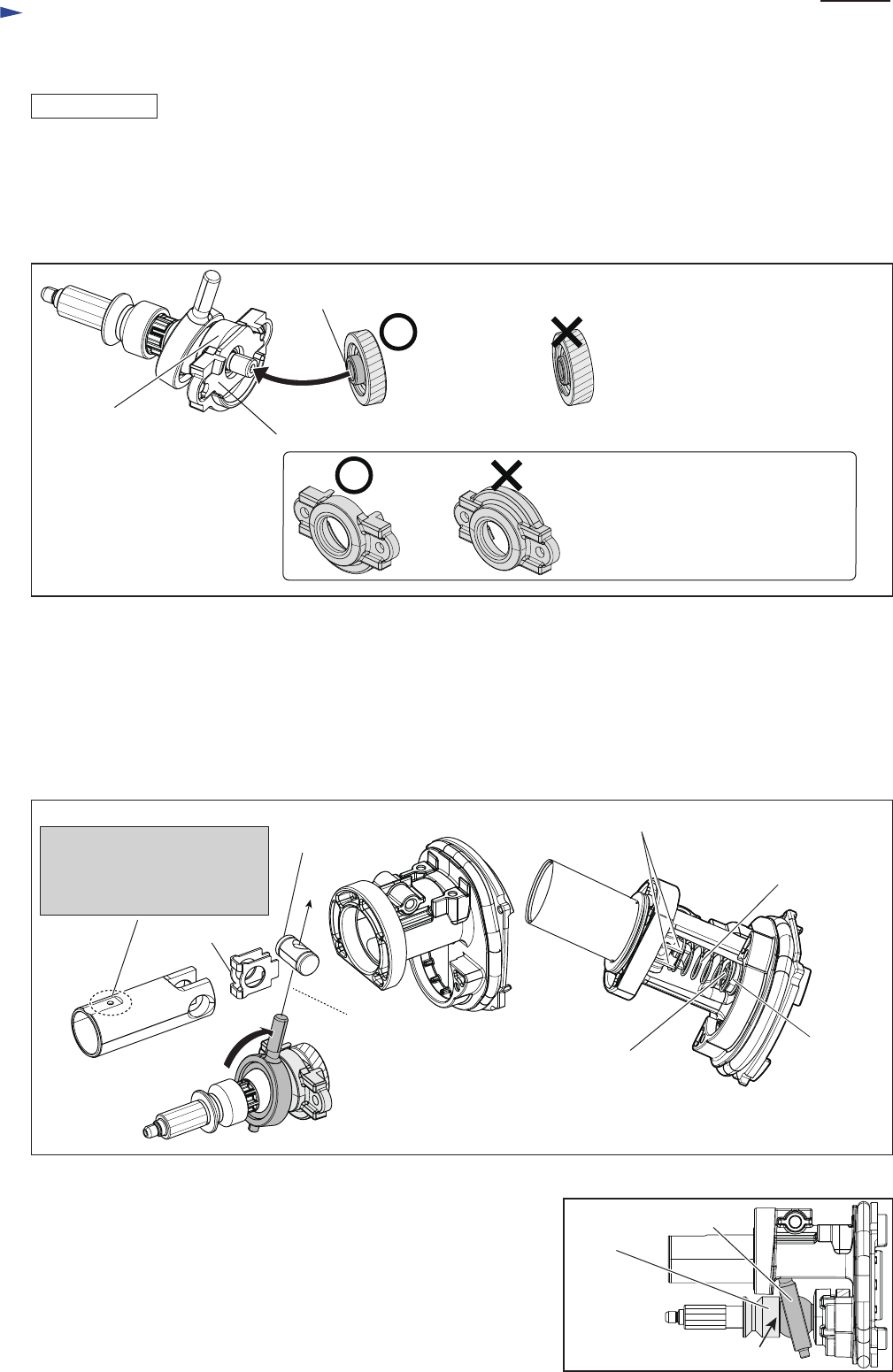
(1) Assemble Guide plate and Piston joint to Piston cylinder. Align the holes of Piston joint to the installed direction of
Swash bearing 10. (Fig. 26)
(2) Set Flat washer 14 and Compression spring 14 on the boss of Inner housing complete. (Fig. 26)
(3) Put the opposite end of Compression spring 14 on Guide plate, then push Piston cylinder into the bottom of Inner
housing complete and insert the pole of Swash bearing 10.
(4) Assemble Striker with O ring 17.5 to Piston cylinder. Refer to Fig 1.
[3] DISASSEMBLY/ASSEMBLY
[3]-7. Swash bearing section (cont.)
The center is projected higher than that of the reverse.
Face the projection to Bearing retainer.
Bearing retainer
Bearing box with
Ball bearing 608ZZ
Helical gear 26
[3]-8. How to assembly of Piston cylinder section to Swash bearing section
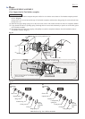
Viewed from
Swash bearing 10 side
The wrong installation causes the top of
Bearing retainer to bump against
Armature shaft.
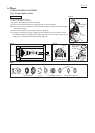
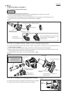
Fig. 27
(1) Check that Clutch cam B is engaged with Swash bearing 10. (Fig. 27)
(2) Assemble Gear housing complete to Inner housing complete.
Check here.
Swash bearing 10
Clutch
cam B
[3]-9. How to assemble Gear housing to Inner housing
Fig. 26
Turn the pole of
Swash bearing 10.
Guide plate
the installed direction of
Swash bearing 10
Viewed from Swash bearing 10
installation side
Boss of Inner housing
complete
Compression spring 14
Guide plate
Flat
washer 14
Piston joint
Note: Air release hole on
Piston cylinder can be
positioned at either
side. (no fixed position)