


P 9/ 13
Repair
Note: 2
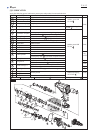
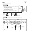
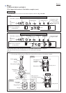
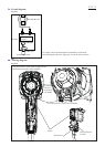
ASSEMBLING
Fig. 18A
Fig. 18B
Cushion ring 12
Ring 10A
O ring case A with
O ring 9 fit inside Impact bolt A
(1) Assemble Impact bolt section to Tool holder complete as drawn in Fig. 18A/ 18B.
Tool holder complete (140264-5)
Impact bolt section in Tool holder complete for HR2600
Impact bolt section in Tool holder complete for HR2601
Sleeve 9A
Bit
installation
side
Inner housing
complete side
O ring case B with
O ring 9 fit inside
ø9mm
ø9.5mm
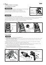
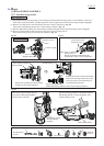
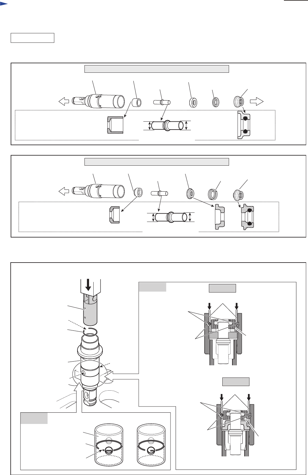
Fig. 19
Note: 1. Use an extra Piston cylinder as a jig. Never use Piston cylinder that is to be assembled to the machine.
2 2 The end gap of Ring spring 28 must not be located at the two holes of Tool holder complete.
(2) Push Ring spring 28 into the inner groove of Tool holder complete as drawn in Fig. 19.
Note: Do not reuse the removed Ring spring 28 if it is deformed or damaged.
Piston cylinder
as a jig
Piston cylinder as a jig
Tool holder
complete
end gap
hole
Inner groove of
Tool holder
complete
Ring spring 28
O ring case A
HR2600
HR2601
Note: These components
are directional.
hole
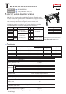
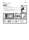
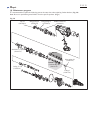
[3] DISASSEMBLY/ASSEMBLY
[3]-6. Impact bolt section in Tool holder complete (cont.)
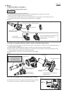
[cross-sectional view]
Ring spring 28
Tool holder
complete
end gap
Ring spring 28
[Correct] [Wrong]
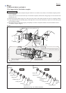
Note: 1
Impact bolt A
Tool holder complete (140265-3)
Bit
installation
side
ø9mm
ø9.5mm
Note: These components
are directional.
[cross-sectional view]
Piston cylinder as a jig
Inner groove of
Tool holder complete
Ring spring 28
O ring case B
Sleeve 9B Washer 10 Compression
spring 20