


7
OPERATING INSTRUCTIONS
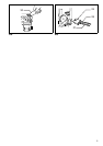
Installing or removing bit
Important:
Always be sure that the tool is switched off and
unplugged before installing or removing the bit.
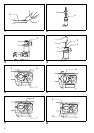
Clean the bit shank and apply the bit grease provided to
it before installing the bit. (Fig.1)
Insert the bit into the tool. Turn the bit and push it in until
it engages. (Fig. 2)
If the bit cannot be pushed in, remove the bit. Pull the
chuck cover down a couple of times. Then insert the bit
again. Turn the bit and push it in until it engages. (Fig. 3)
After installing, always make sure that the bit is securely
held in place by trying to pull it out. To remove the bit, pull
the chuck cover down all the way and pull the bit out.
(Fig. 4)
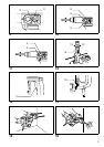
Selecting action mode
When selecting an action mode, first set the change lever
and the shift lever to the position shown in Fig.5. Then
proceed as follows.
Rotation with hammering (Fig. 6&7)
For drilling in concrete, masonry, etc., depress the lock
button and rotate the change lever so that the pointer
points to the h
symbol. Use a tungsten- carbide tipped
bit.
Hammering only (Fig. 6&8)
For chipping, scaling or demolition operations, depress
the lock button and rotate the change lever so that the
pointer points to the
g
symbol. Use a bull point, cold
chisel, scaling chisel, etc.
Rotation only (Fig.6 &9)
For drilling in wood, metal or plastic materials, rotate the
shift lever so that the symbol is aligned with the
pointer on the change lever. Use a twist drill bit or wood
bit.
CAUTION:
• Do not rotate the change lever and/or the shift lever
when the tool is running under load. The tool will be
damaged.
• To avoid rapid wear on the mode change mechanism,
be sure that the change lever and/or the shift lever is
always positively located in one of the three action
mode positions.
• The action mode cannot be changed directly from
“hammering only” to “rotation only” or from “rotation
only” to “hammering only”. First set the change lever
and the shift lever to “rotation with hammering” mode
position shown in Fig. 5. Then set them to the position
for “hammering only” or “rotation only”.
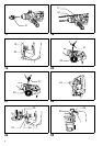
Bit angle
(when chipping, scaling or demolishing)
Important:
Always be sure that the tool is switched off and
unplugged before changing the bit angle.
The bit can be secured at 12 different angles. To change
the bit angle, depress the lock button and rotate the
change lever so that the pointer points to the
O
symbol.
Turn the bit to the desired angle. (Fig. 10)
Depress the lock button and rotate the change lever so
that the pointer points to the
g
symbol.
Then make sure that the bit is securely held in place by
turning it slightly. (Fig.11)
Side grip (Fig. 12)
CAUTION:
• Always use the side grip to ensure operating safety
when drilling in concrete, masonry, etc.
• When the bit begins to break through concrete or if the
bit strikes reinforcing rods embedded in concrete, the
tool may react dangerously. Maintain good balance and
safe footing while holding the tool firmly with both
hands to prevent dangerous reaction.
The side grip swings around to either side, allowing easy
handling of the tool in any position. Loosen the side grip
by turning it counterclockwise, swing it to the desired
position and then tighten it by turning clockwise.
Switch action (Fig.13)
CAUTION:
Before plugging in the tool, always check to see that the
switch trigger actuates properly and returns to the “OFF”
position when released.
To start the tool, simply pull the trigger. Release the trig-
ger to stop.
Speed change (Fig. 14)
The revolutions and blows per minute can be adjusted
just by turning the adjusting dial. The dial is marked 1
(lowest speed) to 6 (full speed). Refer to the table below
for the relationship between the number settings on the
adjusting dial and the revolutions/blows per minute.
Hammer drilling operation (Fig. 15)
CAUTION:
When the bit begins to break through concrete or if the
bit strikes reinforcing rods embedded in concrete, the tool
may react dangerously. Maintain good balance and safe
footing while holding the tool firmly with both hands to
prevent dangerous reaction.
Set the change lever and the shift lever to the
h
symbol.
Position the bit at the location for the hole, then pull the
trigger. Do not force the tool. Light pressure gives best
results. Keep the tool in position and prevent it from slip-
ping away from the hole.
Do not apply more pressure when the hole becomes
clogged with chips or particles. Instead, run the tool at an
idle, then remove from the hole. By repeating this several
times, the hole will be cleaned out.
Number on
adjusting dial
Revolutions per
minute
Blows per
minute
6 720 3,300
5 690 3,150
4 590 2,700
3 490 2,250
2 390 1,800
1 360 1,650