


WARNING: Special attention should be taken to the adjustment because plugging the tool is
required. Don't turn on the main switch for cutting operation of the tool while
adjusting the laser line position. Turn on the switch of laser beam only.
Never look into the laser beam. Direct laser beam may injure your eyes.
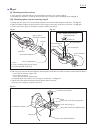
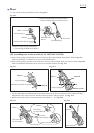
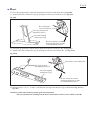
Hex socket set screw M4x6 (A)
Hex socket set screw M4x6 (B)
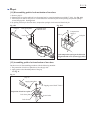
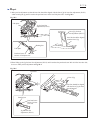
The position of laser line
adjusted to 90
°
against
guide fence
The position of laser line
adjusted to 90
°
against
guide fence
Guide fence
Turn base
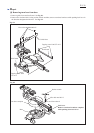
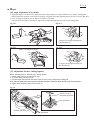
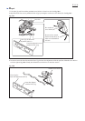
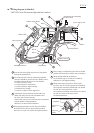
1. Lock the motor unit at the initial position.Mount "Jig for laser line adjustment" (Makita part No. 1R315) to spindle
and drive hex bolt M6x18 into the screw hole of spindle head. See Fig. 20-2.
Fig. 20-1
Fig. 20-A Fig. 20-B
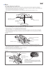
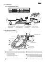
Laser line label
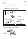
1.Adjustment of the position of laser line can be made with the following screws which are under laser line label.
* Hex socket set screw M4x6 (A): for adjusting 90
°
to turn base See Fig.20-A
* Hex socket set screw M4x6 (B): for adjusting 90
°
to guide fence See Fig. 20-B
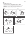
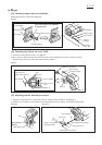
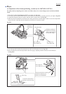
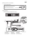
(2) Precise adjustment of laser line
Saw blade
By sliding the position of thumb screw M5x24, user can
select that the laser line is put down either the right side
of blade or the left side.
Laser line
< Note > The position of laser line is factory adjusted in advance within 1mm from the sidesurface of blade.
Jig for laser line adjustment (1R315)
Hex bolt M6x18
(for securing saw blade)
Fig. 20-2
Repair
P 16/ 26
(1) Mechanism for adjustment of the position of laser line