


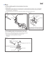
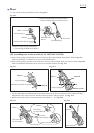
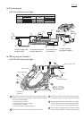
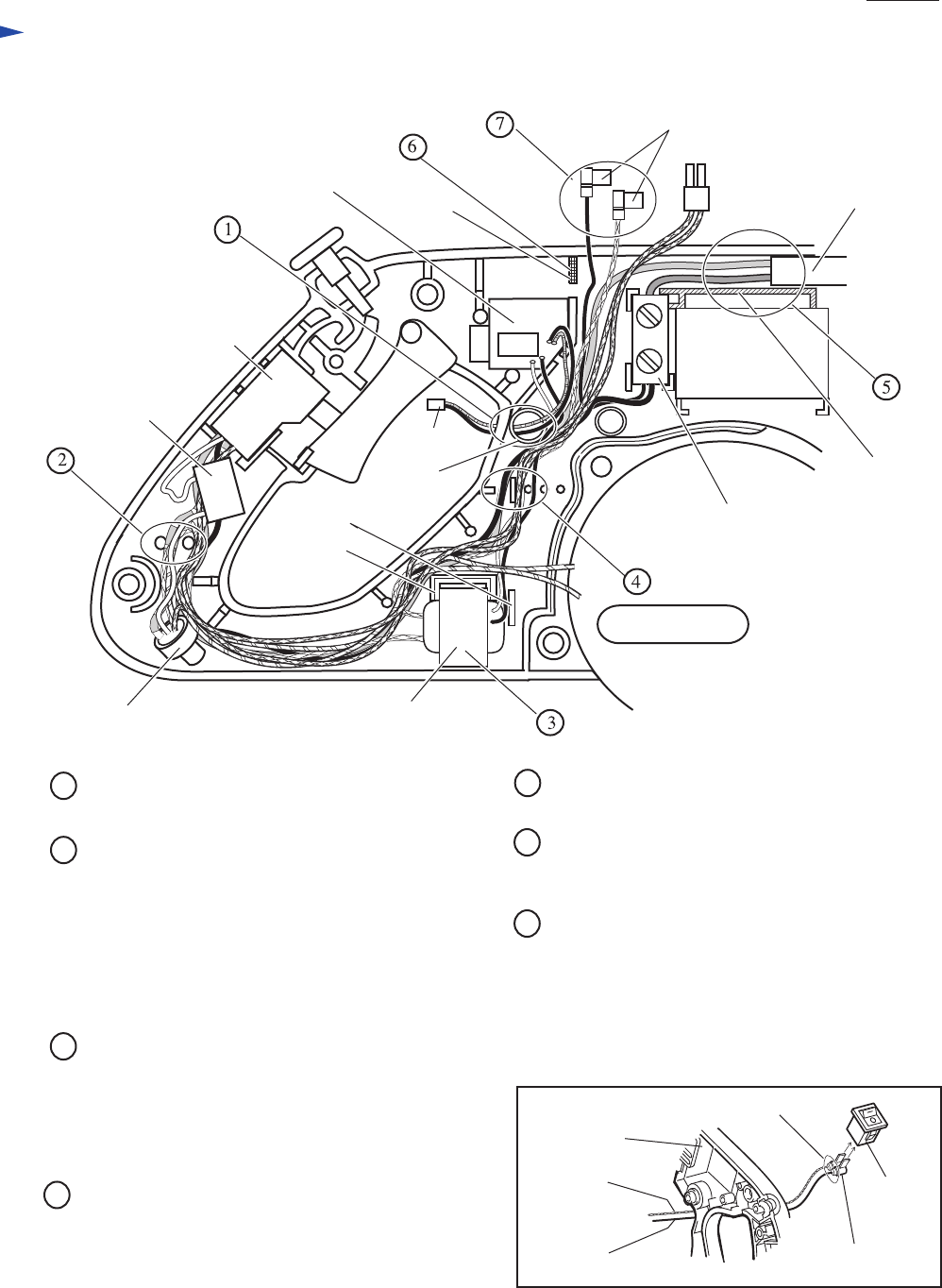
Wiring diagram in Handle L
TransformerInsulated connector
Receptacles for connecting
to laser switch
Power supply cord
Printed wiring board
Rib C
Rib B
Rib A
Terminal block
Motor housing
Rib D
Noise suppressor
Main switch
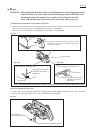
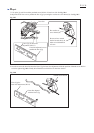
Pass the lead wires (black and red) of wiring board
through the punched hole.
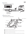
1
2
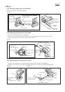
The following lead wires for connecting insulated
connector should be put into lead wire holder so that
insulated connector does not rise from handle L.
* Lead wire (red) to switch
* Lead wire (blue) to transformer
* Lead wire (blue) to light assembly
* Field lead wire (orange)
* Lead wire (white) of noise suppressor
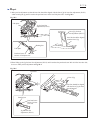
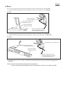
Transformer must be mounted so that lead wires
(black and white) face the side of handle R and
are in the side of motor housing.
If these lead wires go over Rib A/B, these are pinched
between the Rib A/B and handle R.
Therefore, fix them with full attention.
3
5
Power supply cord should be put so that its sheath
portion is between Rib C and the wall of housing L.
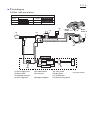
Handle R
Receptacles
Laser
switch
Lead wire
(blue)
Lead wire
(black)
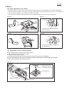
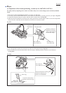
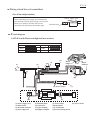
4 When putting the lead wires into lead wire holders,
the thin lead wires have to be put under the thick
lead wires so as not to rise from the original position.
7
When connecting receptacles to laser switch,
be sure to face its wire-accepting side to handle R.
The receptacle with blue colored lead wire should
be close to I mark on the laser switch.
The receptacle with black colored lead wire should
be close to O mark on the laser switch.
See illustration below.
Wire-accepting side
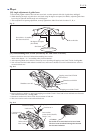
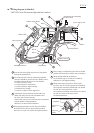
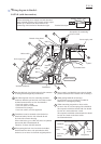
6
When putting handle R on housing L,
be careful not to go over lead wires on Rib D.
Otherwise it will happen pinching.
Punched
hole
Connector
LS0714FL (with Fluorescent light and laser marker)
P 22/ 26