


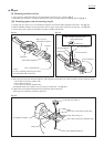
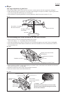
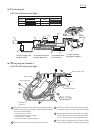
For safety and easy adjusting work, remove saw blade, safety cover section, flanges (outer and inner) and dust
nozzle.
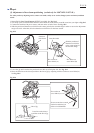
1. Mount Jig for laser line adjustment (1R315) to spindle. See Fig. 20-2.
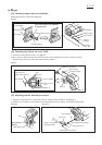
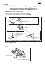
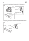
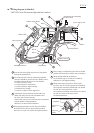
2. Tear away a part of laserline label until hex socket head set screws M4x6 (A and B) come into your sight as Fig.20-5.
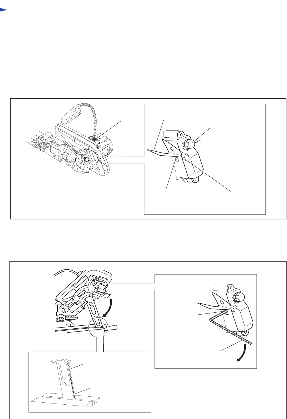
3. Connect the machine with power source, and turn on the switch of laser. See Fig. 20-5.
4. Slide the position of thumb screw M5x24 to the center point for the movable range in order to reserve the adjustment
range to be wide. After that, drive the thumb screw M5x24 to fix the laser section.
Fig. 20-5
Fig. 20-6
(3) Adjustment of laser beam positioning (exclusively for LS0714FL/ LS0714L)
Switch of
laser beam
Slide the position of
thumb screw M5x24
to the center point for
the movable range.
Laser line label
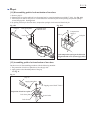
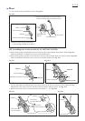
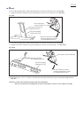
5. Lower the jig until it reaches the pan head screw M5x16 of link plate side. See Fig. 20-3.
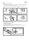
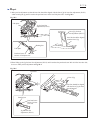
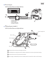
6. Move the laser line to the closest position to the line of jig by adjusting with hex socket set screw M4x6(A).
See Fig. 20-6.
Laser line at the closest
position to the line of jig.
Line of jig
Hex socket set
screw M4x6 (A)
Be sure to turn hex wrench
clockwise and slowly in
order to avoid backlash.
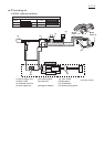
Hex socket set
screw M4x6 (A)
Hex socket set
screw M4x6 (B)
Repair
P 18/ 26