


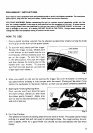
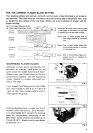

REPLACING INSTALLING PLANER BLADES
After unplugging the tool, you may remove
the planer blades on the tool drum by un-
screwing the three installation bolts with
the socket wrench provided. The clamp
plate comes off together with the blades.
See
Photo.
When you install new
or
sharpened blades,
first clean out
all
chips or foreign matter
adhering to the drum or blades.
Use
blades
of the same dimensions and weight, or
drum oscillation/vibralion will result, caus-
ing poor planing action and, eventually,
tool breakdown.
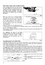
4-c
Fig.
3
Hex. flange
hd.
bo
Drum
Planer
blade
Blade clamp pla
Fig.
4
Screw the blade onto the adjust plate, slip
it
intd the groove
on
the drum, then fit the blade clamp on over it. Fasten with hex flange
hd. bolt.
See
diagram
at
above.
When properly installed, the side of the blade should be flush with the outside edge of the
front and back shoes.
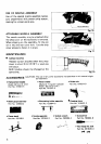
For rabbeting, the edge of the blade
should be made to protrude outside slight-
ly
(0.3
mm
-
0.6
mm
:
1/64”
-
1/32”).
Otherwise, nicks and generally poor rab-
beting results.
Fig.
5
Using blade
gauge
for
even blade setting
Although the blade protrusion for desired cutting depth
IS
easily obtainea by turning the
front knob, the setting of the blade itself in relation to the work may require adjustment
This
is
done conveniently with the blade gauge provided.
First, remove the blade from the tool by unscrewing the hex bolts. Now
set
the blade on
the gauge base
so
that the cutting edge of the blade
is
perfectly flush with the inside sur-
face of the gauge plate. Loosen the screws on the adjust plate (if they are not already
so),
then simply press in the heel of the adjust plate flush with the back side of the gauge base
and tighten the two Phillips screws on top. This insures that your blade tip will be
set
properly when remounted in the tool
so
as
to provide perfectly even planing.
(1)
Set
blade
tip
flush
with
inside
surface
of
gauge
(2)
Press
in
heel
of
adjust
plate
flush
with
back
(3)Tighten
two
Phillips
screws
to
hold
blade
in
plate
sidp
of
gauge
base
place
Fig.
6
4