


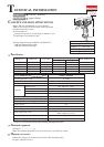
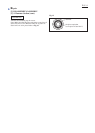
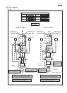
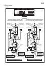
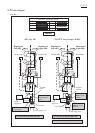
Wiring diagram
P 10/ 14
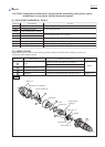
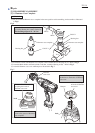
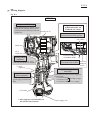
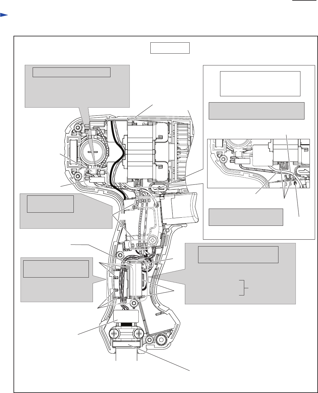
Housing set (L)
Holder arm
Guide Field lead wires (purple, orange)
inside the rib of Holder arm to avoid
pinching between Housing set (R) and
Holder arm.
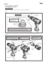
rib of
Holder arm
rib
Field lead
wire (white)
lead wire
holder on
Switch
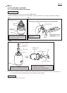
Guide the Lead wires of
power supply cord between
Ribs.
Wiring of Noise suppressor’s
Lead wires
Wiring of Power supply
cord’s Lead wires
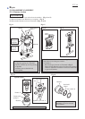
Wiring of Field
lead wires
Wiring around Holder arm
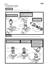
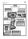
Rib
Rib
Rib
Fix Field lead wires (red, clear)
with lead wire holders on Switch.
Rib
Power supply cord
Lead wire (orange)
of left Brush holder
Wiring of Lead wire (orange)
of left Brush holder and
Field lead wire (white)
Guide Lead wire (orange)
of left brush holder by Ribs.
Guide field Lead wire (white)
between lead wire holder and ribs.
Guide the Lead wires of Noise suppressor
between Ribs.
* Lead wire (black)
* Lead wire (clear)
* Lead wire (white) for Low voltage
for High voltage
** Line filter
** Noise
suppressor
Switch
** Noise suppressor and Line filter are
not used for some countries.
TD0101
Fig. D-2