


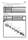
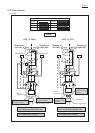
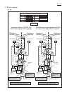
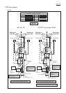
Wiring diagram
P 12/ 14
220-240V area except
Argentine, Chile etc.
Argentine, Chile etc. 220-240V area
where Noise suppression is required
TD0101F
Fig. D-4
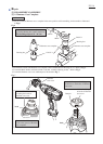
LED Circuit
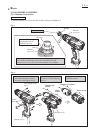
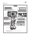
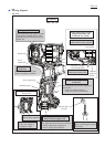
Wiring of Lead wire (brown
or black) of Power supply cord
Through the route between the following
ribs, guide the above lead wire to Switch.
* Ribs for setting Noise suppressor
* Ribs for setting Terminal block
Noise suppressor is
not used for some
countries.
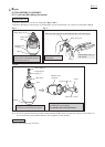
Rib
Put Insulated connector
into the area which is
surrounded by Ribs.
Rib
Field lead
wire (white)
Lead wire
holder on
Switch
Lead wire (orange)
of left Brush holder
Wiring of Lead wire (orange)
of left Brush holder and
Field lead wire (white)
Guide Lead wire (orange)
of left brush holder by Ribs.
Guide field Lead wire (white)
between Lead wire holder and Ribs.
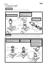
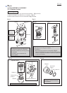
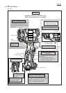
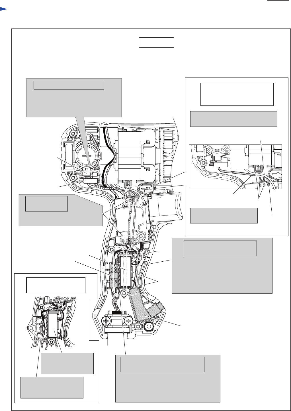
Wiring of Field
lead wires
Fix Field lead wires (red, clear)
with Lead wire holders on Switch.
Guide Field lead wires (purple, orange)
inside the Rib of Holder arm to avoid
pinching between Housing set (R) and
Holder arm.
Wiring around Holder arm
Holder arm
Rib of
Holder arm
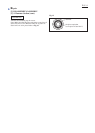
Noise suppressor
Terminal block
Rib
Rib
Wiring of Noise suppressor’s
Lead wires
Guide the Lead wires of Noise suppressor
between Ribs.
* Lead wire (black) to Switch
* Lead wire (black) to LED circuit
* Lead wire (clear) to Field