


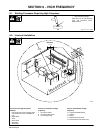
OM-303 Page 14
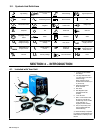
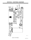
5-4. Electrical Service Guide
S-0092J
. For 230 V models with wall receptacle, 100% duty cycle used to calculate data below. 20% duty cycle used for all other models.
Input Voltage
200 230 380 415 460
Input Amperes At Rated Output 60 52 39 36 33
Max Recommended Standard Fuse Rating In Amperes
1
Time-Delay
2
70 60 45 40 30
Normal Operating
3
90 80 60 50 40
Min Input Conductor Size In AWG
4
10 6 12 12 14
Max Recommended Input Conductor Length In Feet (Meters)
42
(13)
135
(41)
151 (46) 181 (55) 85 (26)
Min Grounding Conductor Size In AWG
4
10 8 12 12 14
Reference: 2005 National Electrical Code (NEC) (including article 630)
1 Consult factory for circuit breaker applications.
2 “Time-Delay” fuses are UL class “RK5” .
3 “Normal Operating” (general purpose - no intentional delay) fuses are UL class “K5” (up to and including 60 amp), and UL class “H” ( 65 amp and
above).
4 Conductor data in this section specifies conductor size (excluding flexible cord or cable) between the panelboard and the equipment per NEC Table
310.16. If a flexible cord or cable is used, minimum conductor size may increase. See NEC Table 400.5(A) for flexible cord and cable requirements.
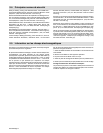
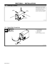
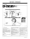
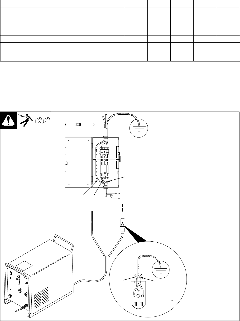
5-5. Connecting Input Power
ST-161 454-A
Tools Needed:
Y Have only qualified persons
make this installation.
Y Disconnect and lockout/tagout
input power before connecting
input conductors for wall recep-
tacle or from unit.
Y Special installation may be
required where gasoline or vola-
tile liquids are present − see NEC
Article 511 or CEC Section 20.
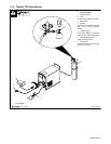
230 Volt Models:
Units come equipped with input power
cord and plug. Wall receptacle is cus-
tomer supplied. To install, select type
and size input and grounding conduc-
tors using Section 5-4. Conductor rating
must comply with national, state, and
local electrical codes.
Install and connect grounding conduc-
tor and input conductors in conduit or
equivalent between wall receptacle and
deenergized line disconnect device.
All Other Models:
Units come equipped with input power
cord for installation into line disconnect
device. Select type and size overcur-
rent protection using Section 5-4.
All Other
Models
230 Volt
Models Only
230 VAC, 1
GND/PE
L1
GND/PE
L2
L1
L2
When making connections in the line
disconnect device, connect the Green
Or Green/Yellow ground conductor first.
Install conductors into a
deenergized line disconnect
device.