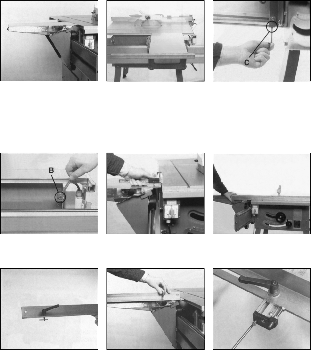
Place table into seats of traversing saddle and
secure with clamp levers (308 & 309). Put a
carriage bolt M6x20 into each of the two holes
and fit with washer B6.4, spring washer B6 and
hex. nut M6. Do not tighten yet.
Slide link bracket extrusion (301) onto heads of
the carriage bolts just installed. Stil bolts need
not to be tightened yet.
The carriage table should be set 0.5 mm (0.020
inch) higher than the saw table. Set by adju-
sting setting screws "C" as required. Make trial
cuts to verify proper operation. Lock counter
nuts of setting screws "C".
4 Support (only for PKS 2300)
- Tap adjustable foot ass'y into square tube with hammer.
- Attach support (347) to roller carrieage extrusion (322) approximately 500 mm/20 in. from the front end.
Use 6 each carriage bolt M8x16, washer A8.4, hex. nut M8. 2 carriage bolt M8x40.
Compensate for uneven floor by turning the adjustable foot ass'y (348) in or out, as required.
The roller carriage extrusion must be set parallel with the machine table by turning setting screw "B", at both front and rear, as required. After setting
lock setting screws in position with counter nuts.
Place ratched lever M8x20 through slot of link
bracket angle bar (307) and attach slide was-
her (329) to threaded pin of ratched lever.
Slide slide washer (329) into recess of link
bracket extrusion (301). Insert mandrel and
lock by lightening starknob screw.
Attach link bracket extrusion end plate (357) to
link bracket extrusion with two countersunk
head tapping screws Ø 4.8x22. Set fence square
to sawblade and slide link bracket extrusion as
required to set to ZERO position. Now fully
tighten the two carriage bolts holding the link
bracket extrusion to the table. Fine tune fence
position with setting screw (414) fitted into link
bracket extrusion end plate (357). Set scale as
required to obtain exact setting.


