


6
MS6720 INSTALLATION: POWERED BY HOST DEVICE
If the host system supplies +5VDC power to the scanner, reposition the
internal jumper within the MCA (Metrologic C
onnector Adapter) before
connecting the scanner to the host device. In addition, plug the 4 position
ground jumper into the power supply connector located on the side of the
MCA.
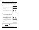
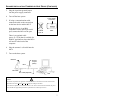
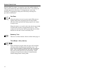
1. Make sure the MCA is not connected to the
scanner, communication cable or host and
unfasten the case.
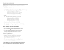
2. Reposition the shunt on JP1 to pins 1 and 2
and close the case.
The factory setting of jumper 1 (JP1) is on pins 2
and 3. To direct power for the scanner from the
host device, position the jumper on pins 1 and 2.
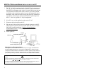
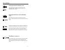
Pin 1 of the MCA provides a connection point
for various ground/shield ground configurations
on different Metrologic products. Internal
jumper JP2 of the MCA gives end users the
option of changing pin 1 of the DB9 into a no
connect (NC). Simply remove the jumper from
the pins, then pin 1 of the DB9 becomes an
open/no connect pin.
JP2 should ALWAYS be in place for OCIA
applications.
Continued on next page
Caution:
*To maintain compliance with applicable standards, all circuits connected to the scanner must meet the
requirements for SELV (Safety Extra Low Voltage) according to EN 60950.
**To maintain compliance with standard CSA C22.2 No. 950/UL 1950 and norm EN 60950, the power
source should meet applicable performance requirements for a limited power source.
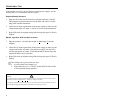
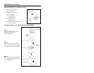
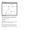
Top View of Header, Pins, and Jumper
HOST
JP1
Regulated +5VDC
Power Supply
(Factory Setting)
JP1
+5VDC Host
Power
HOST
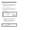
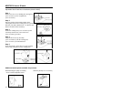
1
3
1
3
Jumper removed
for open/no
connect pin
Factory Setting
JP2
Top View of Pins, and Jumper