


35
APPENDIX C
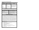
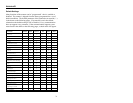
Pin Assignments for the Coil Cable
The MS6720 scanners are terminated to a 10 position shielded modular
connector. All coil cables (
MLPN 44-44780) for the MS6720 scanner are
terminated the same. The difference between versions is the end of the
cable going into the scanner. This connector plugs into different “J”
positions on various computer/interface boards. Since each
computer/interface board is different, the output signals are different.
Version “9” (OCIA) Version “11” (46XX)
Pin Function Pin Function
1 Power/Signal Ground 1 Power/Signal Ground
2 RDATA 2 RS-232 Transmit Output
3 RDATA Return 3 RS-232 Receive Input
4 Clock In 4 RTS Output
5 Clock In Return 5 CTS Input
6 Clock Out 6 IBM 46XX Transmit
7 Clock Out Return 7 IBM 46XX Receive
8 No Connection 8 No Connection
9 +5 VDC Power to Scanner 9 +5 VDC Power to Scanner
10 OCIA Shield Ground 10 Shield Ground
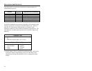
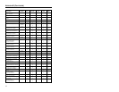
Version “14” (232) Version “15” (LTPN)
PinFunction Pin Function
1 Power/Signal Ground 1 Power/Signal Ground
2 RS-232 Transmit Output 2 RS-232 Transmit Output
3 RS-232 Receive Input 3 RS-232 Receive Input
4 RTS Output 4 RTS Output
5 CTS Input 5 CTS Input
6 DTR Input 6 Light Pen Source +5V
7 DSR Output 7 Light Pen Data
8 No Connection 8 No Connection
9 +5 VDC Power to Scanner 9 +5 VDC Power to Scanner
10 Shield Ground 10 Shield Ground